Applied Thermoelectric Solutions LLC

Wireless Power for Rotating Shaft Sensors | PowerBeam™
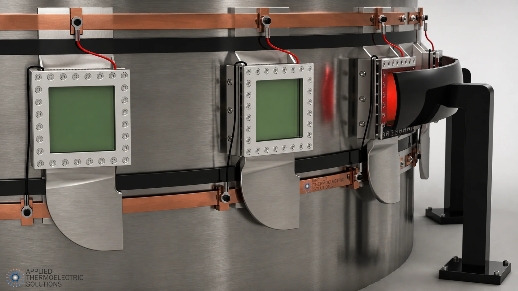
Persistent power for continuous insight into rotating machinery
An unforeseen outage can cost approximately $30,000 per day for a small hydropower generating unit and up to $800,000 per day for a large unit.
Continuous rotor monitoring can help operators identify developing conditions, plan maintenance, and avoid unnecessary outages. But sensors and data-acquisition systems mounted directly on a rotating shaft can provide that insight only while they have reliable power.
PowerBeam™ is a patented thermoelectric generator (TEG) based radiant wireless-power architecture designed to create a persistent, regulated DC power supply on large rotating shafts.
Stationary radiant-energy sources transfer controlled energy across an air gap to thermoelectric receiver assemblies mounted on the shaft. The receivers convert absorbed energy into electrical power for sensors, data-acquisition systems, telemetry, edge processing, and other shaft-mounted electronics.
PowerBeam™ is being developed for rotating assets where battery replacement or recharging is costly, sliding electrical contacts are undesirable, power is required at zero and variable speed, and installing a close-coupled electromagnetic power-transfer structure may be difficult.
Reclamation Phase I selection | Two issued U.S. patents | Mature technology building blocks
Selected from more than 300 competition entries
PowerBeam™ was developed in response to the Bureau of Reclamation’s Powering Electronic Equipment on a Rotating Shaft competition, conducted with InnoCentive in partnership with the U.S. Army Corps of Engineers, Bonneville Power Administration, and the Department of Energy.
The competition attracted more than 300 entries from an international field. Its planned two-phase reduction-to-practice structure included a $50,000 Phase I concept purse and a $200,000 Phase II prototype-evaluation purse, for a total announced prize pool of $250,000.
The PowerBeam™ concept was selected for a $5,000 Phase I prize and advancement to the prototype round.
Applied Thermoelectric Solutions declined the prize because accepting it would have required granting a non-exclusive license covering the patented solution. The decision preserved the company’s intellectual-property and licensing strategy; it was not a technical rejection of the concept.
Recognition status: Selected for a Phase I award and prototype-development opportunity; award declined to preserve patent-licensing rights.
Technology snapshot
| Area | Current status |
|---|---|
| Technology | PowerBeam™ patented radiant wireless-power architecture for rotating-shaft sensors and electronics |
| System-level readiness | TRL 2 — patented, formulated, and computationally modeled as a complete integrated system |
| Component heritage | Established or previously demonstrated thermoelectric generators, radiant sources, heat pipes, fins, heat exchangers, thermal interfaces, optical materials, selective surface treatments, and power-conditioning electronics |
| PowerBeam-specific development | Receiver integration, shaft mounting, radiant coupling across the operating clearance, stationary and rotating heat rejection, source controls, structural validation, and regulated shaft-side DC output |
| Next milestone | TRL 3 — integrated bench-scale experimental proof of concept |
| Initial design target | 1–20 W at 9–30 VDC |
| Power architecture | Modular and scalable shaft-side regulated DC bus |
| Intellectual property | Two issued U.S. patents and one allowed Canadian patent application |
| Commercial status | Available for licensing, co-development, prototype validation, and industry-supported SBIR collaboration |
| Partners sought | Hydropower operators, turbine and generator OEMs, rotating-telemetry companies, condition-monitoring providers, service organizations, and research institutions |
PowerBeam™ is classified at TRL 2 at the complete integrated-system level because its architecture and analytical models have been developed, but its critical PowerBeam-specific functions have not yet been demonstrated together experimentally. Many constituent technologies are commercially mature or have been demonstrated in related applications, reducing component-development risk. TRL 3 requires laboratory testing that physically validates the integrated system’s analytical predictions.
Reliable rotor monitoring requires reliable rotor power
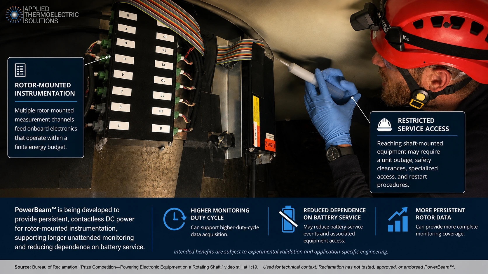
Direct measurements from a rotating shaft can reveal mechanical and electrical conditions that may be difficult to observe adequately from stationary sensors.
Measurements of strain, temperature, vibration, torque, acceleration, and electrical behavior can help operators:
- Identify developing damage
- Monitor a known defect or temporary repair
- Capture startup, shutdown, trip, and load-change events
- Estimate accumulated fatigue
- Plan maintenance before taking equipment out of service
- Reduce unnecessary inspection outages
- Improve confidence in continued operation
The challenge is keeping the instrumentation powered for as long as the condition must be monitored.
Battery-powered systems can provide valuable measurements, but their available onboard energy is finite. Sensor count, bridge excitation, sampling rate, onboard processing, transmission frequency, and monitoring duration must all be managed within the battery’s capacity.
In one documented Reclamation application, battery-powered wireless nodes acquired data from 16 rotor-mounted strain gauges used to monitor a repaired hydrogenerator rotor-spider crack. The system was designed to conserve battery energy by sleeping most of the time and waking during selected operating events or timed intervals. Reclamation estimated that avoiding monthly inspection outages allowed the unit to remain online for one year and produced approximately $1 million in savings; the report notes that the savings estimate was not peer reviewed.
PowerBeam™ is intended to expand what this type of monitoring system can do by supplying an external, persistent source of shaft-side power.
The opportunity is not merely to replace a battery. It is to make direct rotor instrumentation continuously available when the measurement is valuable.
Persistent power can support:
- Higher measurement duty cycles
- More sensors and measurement channels
- Continuous low-rate trending
- Longer high-rate event recordings
- More onboard processing
- More frequent communication
- Continuous sensor and system health checks
- Longer unattended monitoring campaigns
- Capture of events not anticipated when the trigger strategy was established
The rotating-shaft power challenge

Reclamation was not seeking power for only one ultra-low-power sensor. It defined a demanding combination of electrical, mechanical, environmental, and installation requirements.
| Initial application requirement | Reclamation target |
|---|---|
| Continuous electrical output | 1–20 W |
| Regulated output voltage | 9–30 VDC |
| Shaft diameter | 18–144 inches |
| Rated rotational speed | 72–550 RPM |
| Maximum design speed, including overspeed | Up to 935 RPM |
| Centrifugal loading | Up to 224 g |
| Operation at zero speed | Required |
| Shaft-mounted mass | No more than 6 lb |
| Installation labor | Fewer than 10 staff-hours |
| Shaft modification | No drilling, tapping, or welding |
| Installation outages | One outage without later adjustment |
| Intended service | Short-term and more than five years |
Reclamation’s current public summary lists rated speeds of 72–550 RPM. The detailed original competition requirements extended the design envelope to 935 RPM to account for overspeed. The system also had to operate at standstill and while accelerating or decelerating.
The desired solution was expected to tolerate vibration, humidity, airborne contaminants, electromagnetic interference, and temperatures typical of a powerplant environment. Additional preference was given to a regulated, nonchemical power source that could operate before rotation began and after it stopped without requiring stationary hardware around the shaft’s complete circumference.
Installation was itself an important part of the problem. A technically effective system could still be uneconomic if it required:
- Extended machine disassembly
- Multiple generating-unit outages
- Permanent shaft modifications
- Extensive precision adjustment
- Heavy shaft-mounted hardware
- A large circumferential stationary support structure
PowerBeam™ was conceived around this complete requirement set rather than around power output alone.
How PowerBeam™ works
1. A stationary source transmits radiant energy
One or more stationary sources direct controlled radiant energy toward receiver assemblies mounted on the rotating shaft.
The patented architecture is not limited to infrared or to one source technology. Potential sources include:
- Ceramic and quartz thermal emitters
- Carbon emitters
- Narrowband solid-state emitters
- Infrared sources
- Laser sources
- Gas-fired radiant sources
- Fiber-guided concentrated solar energy
- Other controllable radiant sources
The source can be selected according to:
- Required radiant power
- Source-to-receiver distance
- Beam or illumination area
- Wavelength
- Switching response
- Source life
- Installation geometry
- Safety and guarding requirements
- Cost and serviceability
The patents contemplate laser beams, infrared heaters, flames, concentrated solar energy, ceramic heaters, carbon heaters, quartz lamps, and other sources capable of directing radiant energy toward the receiver.

2. The receiver captures and contains the energy
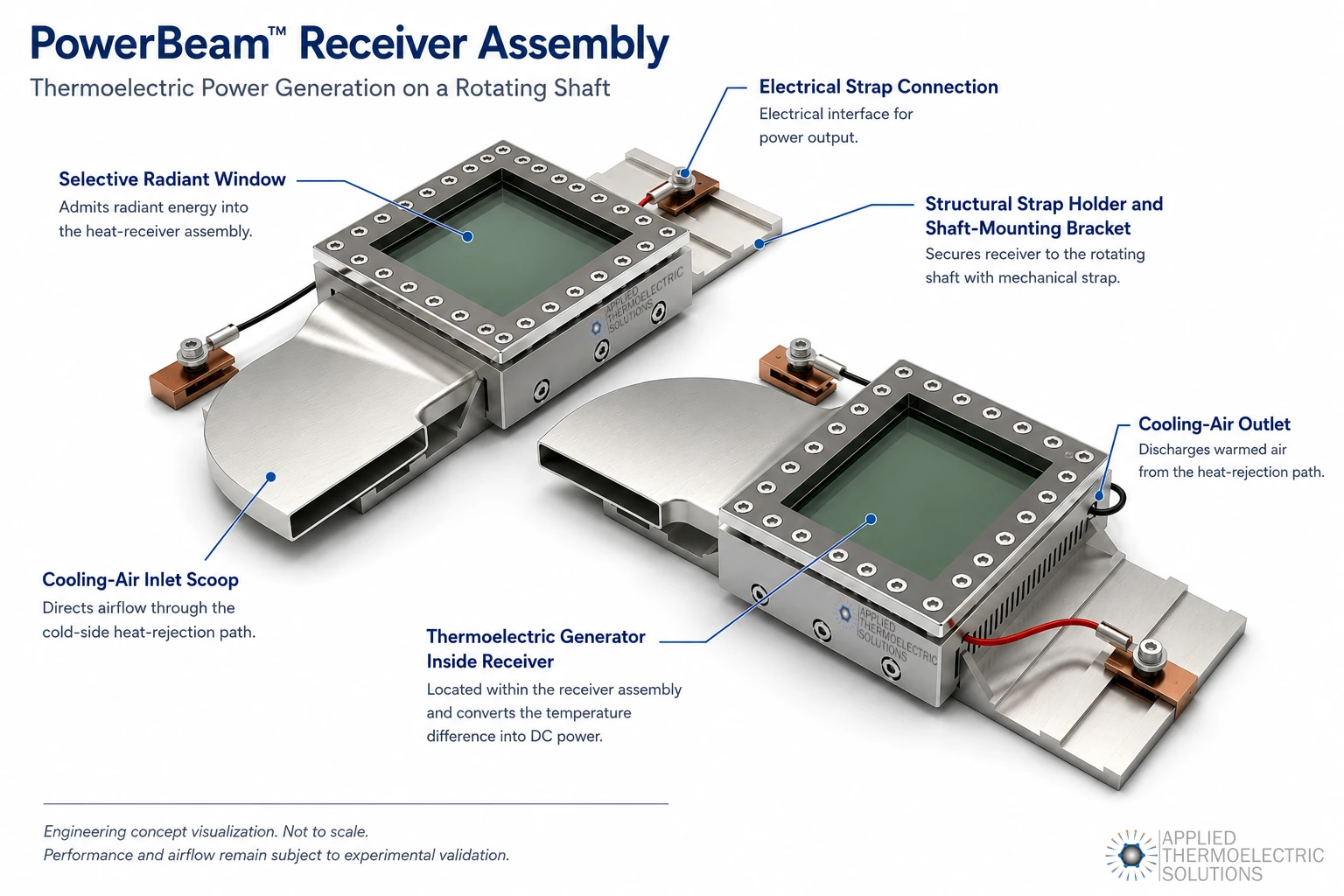
Radiant energy enters a shaft-mounted receiving structure designed to absorb useful energy while reducing reradiation and convective heat loss from the hot side.
The receiver architecture may include:
- A radiant-energy receiving window
- Reflective and absorptive surfaces
- A thermally isolated interior region
- A heat-transfer plate
- A sealed, inert-gas-filled, or partially evacuated cavity
- Structural reinforcement for rotating operation
- Shielding between the receiver and shaft
These features help establish and retain the temperature difference required by the thermoelectric generator.
3. Thermoelectric generators create DC power
Thermoelectric generator modules convert the temperature difference and a portion of the heat flow directly into DC electrical power through the Seebeck effect.
Modules and receiver assemblies can be connected in series or parallel to produce the required voltage and current. Maximum-power-point control and DC-DC electronics can regulate the raw thermoelectric output for the connected instrumentation.
Because the thermoelectric modules inherently generate DC, the rotor-side system does not require a high-frequency rectifier as part of the energy-conversion interface. Power-conditioning electronics would still be used for:
- Maximum-power-point operation
- Cold startup
- Voltage regulation
- Load transients
- Charging capacitors or secondary storage
- Fault management
PowerBeam™ is intended to create a usable shaft-side DC power bus rather than supplying power only to one proprietary telemetry transmitter.

4. Integrated thermal management rejects the remaining heat
Thermal management is a fundamental part of the PowerBeam™ architecture.
The receiver can incorporate:
- Heat spreaders
- Heat pipes
- Finned heat exchangers
- Natural convection while stationary
- Rotation-enhanced convection
- Thermal capacitance
- Phase-change materials
- Thermal shielding between the receiver and shaft
- Control of source power based on shaft speed and temperature
The finned and heat-pipe configurations were developed in part to support passive heat rejection when the shaft is stopped and rotation-induced airflow is unavailable.
PowerBeam™ was designed as a complete thermal-to-electrical system. Receiving, containing, transporting, and rejecting heat are integral to the architecture—not secondary packaging added after choosing the energy converter.
The patents describe heat-dissipation systems and controlled convection cooling intended to operate both when the shaft is stationary and when rotation produces a higher-velocity airstream.
Designed for the complete machine operating cycle
Many hydropower, turbine-generator, marine, and industrial shafts do not stop at a guaranteed angular position. Their final position may depend on operating conditions, hydraulic or mechanical forces, friction, braking, and shutdown timing.
A localized power transmitter can become ineffective at standstill if its receiver stops outside the useful transfer region.
PowerBeam™ can address this through an application-specific combination of:
- Multiple stationary radiant sources
- Multiple rotating receiver assemblies
- Wide source coverage
- Overlapping receiving regions
- Thermal energy storage
- Electrical ride-through storage
The source coverage and receiver positions can be selected so that one or more receiver assemblies remain within a useful radiant region at any final shaft position—without requiring a close stationary power-transfer structure around the entire shaft circumference.
The receiver’s thermal mass is also intended to average intermittent radiant input into a more stable temperature difference. During rotation, the electrical output does not need to follow each brief passage through a source field instantaneously.
At the original operating-speed range, each receiver could pass through illuminated and nonilluminated regions many times per minute. If the receiver’s thermal time constant is substantially longer than each interruption, the hot-side temperature and electrical output should remain considerably smoother than the instantaneous radiant input.
Bench testing will quantify:
- Minimum power at every stopped angle
- Output ripple during rotation
- Thermal time constant
- Startup response
- Short-duration ride-through
- Performance during changing speed
- Natural-convection capability at standstill
- Required electrical storage for longer interruptions
Why consider PowerBeam™?
Persistent power at zero and variable speed
Power is supplied from an external, controlled source rather than being generated from rotation, vibration, airflow, or another motion-dependent input.
The architecture can therefore support monitoring:
- Before startup
- During startup
- At normal operating speed
- During load changes
- During shutdown
- After the shaft stops
No sliding electrical power contact
PowerBeam™ transfers energy across an air gap without a sliding electrical connection between stationary and rotating assemblies.
This eliminates:
- Sliding-contact wear
- Brush-generated debris
- Slip-ring contact-surface maintenance
- Contact inspection and replacement
- Electrical noise associated with a degrading sliding interface
Reduced dependence on finite onboard energy
A small capacitor or rechargeable battery may still be useful for peak loads, fault logging, communication bursts, or short interruptions. Routine monitoring, however, does not have to be constrained by the total energy stored in a primary shaft-mounted battery.
This can allow the monitoring strategy to be selected according to the mechanical condition rather than according to battery conservation.
No close magnetic power-transfer interface
PowerBeam™ does not rely on transformer coupling between a rotating coil and a stationary pickup.
This can be advantageous where:
- A close concentric pickup cannot be installed
- Radial clearance is large or variable
- Complete circumferential access is restricted
- Shaft runout or structural movement complicates a magnetic coupling gap
- Nearby conductive or magnetic structures affect system integration
- Discrete stationary source locations are easier to retrofit
- A large shaft makes a continuously close stationary structure difficult to support
- The required shaft-side load exceeds the available output of a telemetry-specific coupler
Commercial inductive telemetry performs well in many applications. PowerBeam™ addresses a different architecture in which radiant access may be easier to establish than a close electromagnetic coupling structure.
Greater geometric tolerance by design
PowerBeam™ requires an unobstructed and sufficiently strong radiant path, but it does not depend on maintaining a narrow transformer-style coupling gap.
A broad source field and comparatively large absorbing receiver provide an engineering basis for accommodating moderate:
- Radial movement
- Axial offset
- Angular variation
- Receiver tilt
- Shaft runout
- Partial source displacement
Tolerance can be increased through:
- Source coverage
- Receiver area
- Reflectors
- Source placement
- Multiple receivers
- Multiple transmitters
The actual distance, offset, tilt, runout, and obstruction limits will be measured during bench testing.
Modular power and geometry
The initial system was modeled around Reclamation’s 1–20 W requirement, but 20 W is not a fundamental technology limit.
Power can be adapted through:
- Receiver area
- Thermoelectric module size and selection
- Module count
- Receiver count
- Source power
- Source coverage
- Series and parallel electrical connections
- Heat-rejection capacity
The practical limit for a particular machine will be determined by:
- Available space
- Allowable rotating mass
- Radiant access
- Receiver heat rejection
- Source power
- Mechanical loading
- Required voltage and current
PowerBeam™ is therefore better understood as a scalable rotor-power architecture than as a fixed 20 W product.
Broad source flexibility
A thermoelectric receiver converts absorbed heat rather than relying on a semiconductor bandgap matched to one optical wavelength.
This creates the potential to use:
- Broad-spectrum thermal sources
- Narrowband emitters
- Lasers
- Concentrated solar energy
- Mixed source technologies
- Sources selected around local energy availability or installation geometry
Integrated thermal buffering
The absorber, heat-transfer structure, thermoelectric modules, heat spreader, heat pipes, and other thermal mass can buffer short variations in received radiant energy.
This may provide:
- Smoother output during rotation
- Ride-through during brief obstruction
- Reduced dependence on continuous optical overlap
- More stable thermal conditions for the power electronics
- Reduced electrical-storage requirements for short interruptions
Why consider PowerBeam™?
PowerBeam™ is not intended to replace every rotating-shaft power technology. The best method depends on required power, geometry, operating cycle, stop position, installation access, environment, and lifecycle cost.
| Approach | Principal strengths | Important application considerations |
|---|---|---|
| Battery | Simple, familiar, operates at zero speed, little stationary hardware | Finite stored energy; rotating mass; recharge or replacement access; monitoring-duty-cycle compromises; mechanical containment under centrifugal loading |
| Slip ring | Mature; continuous power; high power capability; operates at standstill | Sliding-contact wear; brush debris; inspection and replacement; rotating and stationary hardware integration; installation may require substantial machine access or modification |
| Inductive transfer | Commercially established; efficient; battery-free; can combine power and data; operates at standstill when continuously coupled | Requires a defined magnetic coupling geometry; allowable gap, overlap, runout, shaft diameter, external load power, and installation method vary by design; circumferential hardware and stationary supports may complicate some large-machine retrofits |
| Capacitive transfer | Contactless; no magnetic core required; can support meaningful power | Controlled electrode geometry and gap; high-frequency or high-voltage electronics; electric-field management; surrounding conductive structures; retrofit complexity |
| RF or microwave power | Spatial freedom for very-low-power instrumentation; no close mechanical coupler | Usable received power, antenna area, efficiency, shielding, and regulatory constraints become more significant as required load increases |
| Motion or vibration harvesting | No stationary transmitter; attractive for ultra-low-power sensing during predictable motion | Output depends on speed, vibration, airflow, or another mechanical input; limited or unavailable power during standstill; generally better suited to lower-power loads |
| Optical/PV transfer | High conversion efficiency and receiver power density with a matched source | Requires optical overlap, line of sight, spectral matching, receiver cooling, safety controls, and electrical storage or overlapping illumination during interruptions |
| PowerBeam™ | Persistent DC output; broad source options; thermal buffering; distributed geometry; no sliding contact or magnetic coupler; modular scaling beyond the initial application range | Requires radiant access, receiver heat rejection, source and hot-surface safety controls, appropriate shielding, and bench validation |
Installation is a critical part of the comparison. A technology that performs well electrically may still be uneconomic if installation requires:
- Machine or turbine disassembly
- A prolonged outage
- Extensive stationary support hardware
- Permanent shaft modification
- Precision adjustment in a difficult-access area
- Additional outages for later alignment
- Excessive shaft-mounted weight
PowerBeam™ is intended for applications where persistent rotor power is needed but finite batteries, sliding contacts, motion-dependent generation, or a close electromagnetic coupling structure create undesirable installation or lifecycle tradeoffs.
When is PowerBeam™ a strong candidate?
PowerBeam™ may merit a feasibility evaluation when several of the following conditions apply.
The instrumentation requires persistent power
The system must remain available for extended monitoring rather than being interrupted periodically for battery replacement or recharging.
Power is required while the shaft is stationary
Important measurements may occur before startup, during startup, after shutdown, or while observing a stationary defect or temporary repair.
The load exceeds a typical ultra-low-power sensor
The application requires:
- Bridge excitation
- Multiple sensors
- Data acquisition
- Onboard processing
- High-rate telemetry
- Active calibration
- Sensor heating
- Redundant electronics
- Several watts or more of regulated DC power
Battery access is expensive
Servicing the rotating instrumentation may require:
- A generating-unit outage
- Lockout and clearance procedures
- Rotor restraint
- Guard removal
- Specialized access
- Scaffolding or lifting equipment
- A lengthy restart and verification process
The cost of the access event may greatly exceed the cost of the battery itself.
Final shaft position is uncertain
A localized receiver cannot be assumed to stop directly in front of a single stationary transmitter.
A close circumferential coupler is difficult to install
The machine lacks:
- Radial clearance
- Complete circumferential access
- A stable stationary support structure
- A suitable close-coupling geometry
- Adequate axial space
- An economical path for custom installation
A radiant path can be established
One or more accessible stationary positions can direct energy toward receiver assemblies without unacceptable obstruction.
The receiver can reject heat safely
The installation has sufficient space, airflow, and thermal isolation for the required heat-spreading, heat-pipe, fin, and shielding systems.
Better rotor data can change a maintenance decision
The measurement can:
- Reduce inspection frequency
- Improve remaining-life estimates
- Support continued operation
- Shorten an outage
- Identify a developing condition sooner
- Increase confidence in a temporary repair
- Improve the coverage of startup, shutdown, trip, or load-change events
When most of these conditions are present, PowerBeam™ may offer a combination of capabilities that batteries, slip rings, motion harvesters, localized optical systems, and close-coupled induction do not provide economically in the same installation.
Initial applications

Hydropower-generator rotor monitoring
PowerBeam™ was initially developed for instrumentation mounted on large hydroelectric generator and turbine shafts.
Potential measurements include:
- Rotor-spider and rotor-rim strain
- Shaft torsional strain
- Rotor temperature
- Local vibration and acceleration
- Electrical and magnetic behavior
- Conditions associated with a temporary repair
- Startup, shutdown, trip, and load-change events
Reclamation’s condition-monitoring program has already demonstrated that direct rotor-mounted strain measurement can support continued operation of a unit with a repaired rotor-spider crack and avoid repeated visual-inspection outages.
Extended monitoring of known defects
A particularly strong initial application is long-duration monitoring after:
- A crack
- A temporary repair
- An unusual inspection finding
- Unexpected strain or vibration
- Rotor-rim movement
- A localized condition not observable from stationary sensors
In these cases:
- The monitoring requirement already exists
- Direct rotor measurements have defined operational value
- The monitoring period may last months or years
- Repeated physical inspection may require outages
- Missing an unexpected event may carry substantial consequences
- Additional sensor power may expand the monitoring strategy
Large turbine-generators
Steam, gas, nuclear, and other turbine-generator trains may require permanent:
- Torsional-strain monitoring
- Rotor-temperature monitoring
- Local vibration measurement
- Electrical-condition measurement
- Shaft-mounted edge processing
PowerBeam™ may be relevant where a very-low-power RF system is insufficient and close full-circumference electromagnetic hardware is difficult to install or qualify on an existing shaft.
Other large rotating assets
Applications for evaluation include:
- Large industrial motors and generators
- Marine propulsion shafts
- Rolling mills
- Compressors
- Pumps
- Mining and process equipment
- Large rotating test systems
Suitability will depend on:
- Required power
- Rotational speed
- Shaft movement
- Stop position
- Available radiant path
- Environmental conditions
- Allowable rotating mass
- Receiver heat-rejection capability
- Installation access
- Economic value of uninterrupted monitoring
Development Status: Proven Building Blocks, New System Integration
PowerBeam™ is currently at TRL 2 as a complete rotating-shaft wireless-power system. The system architecture has been formulated, patented and computationally modeled, but a complete physical PowerBeam™ assembly has not yet been built and experimentally demonstrated. Applied Thermoelectric Solutions supports this work through thermoelectric design and simulation services that evaluate thermal, electrical, and system-level behavior before prototype testing.
The system does not depend on every component being developed from the ground up. PowerBeam™ combines established or commercially available technologies, including thermoelectric generators, radiant-energy sources, heat pipes, finned heat exchangers, thermal interfaces, optical materials and power-conditioning electronics. Selective absorbers, transmissive optical windows, anti-reflective coatings and low-conduction enclosures have also been demonstrated in related solar-thermoelectric and radiative-energy applications.
The principal remaining development work is the application-specific integration of these technologies into a complete shaft-mounted system. Key validation areas include radiant-transfer performance across the operating clearance, stationary and rotating heat rejection, structural durability, shaft-position tolerance, regulated DC output, thermal and electrical controls, installation and long-term operation.
| Area | Current maturity |
|---|---|
| TEG modules, heat pipes, fins, heat exchangers, and thermal interfaces | Established technologies with commercial and experimental heritage |
| Radiant sources, optical materials, and selective surface treatments | Established in optical, solar-thermal, and related TEG applications |
| TEG power conditioning, voltage regulation, and energy storage | Established circuit functions requiring PowerBeam-specific selection and integration |
| PowerBeam™ receiver architecture, shaft mounting, radiant coupling, source control, and system integration | Patented and computationally modeled; requires experimental validation |
| Complete integrated PowerBeam™ system | TRL 2 |
| Next development milestone | TRL 3 integrated bench-scale experimental proof of concept |
Next Milestone: TRL 3 Integrated Experimental Proof of Concept
The next development phase will combine representative mature components into a bench-scale PowerBeam™ assembly and experimentally validate the PowerBeam-specific radiant-transfer, thermal, electrical, control, and mechanical functions. The detailed validation program is outlined below.
Proposed bench-validation program
Radiant-source characterization
This program follows Applied Thermoelectric Solutions’ thermoelectric system development process, progressing from feasibility and modeling through prototype engineering, testing, and validation.
Candidate source classes will be compared, including:
- Broad-spectrum thermal emitters
- Narrowband solid-state emitters
- Laser sources
Testing will measure:
- Electrical input
- Useful radiant output
- Source temperature
- Beam or field area
- Switching response
- Source-to-receiver distance
- Receiver coupling
- Cooling requirements
- Safety requirements
- Expected service life
Power versus geometry
Regulated electrical output will be measured as a function of:
- Source-to-receiver distance
- Radial offset
- Axial offset
- Receiver angle
- Shaft runout
- Partial obstruction
- Source coverage
- Shaft stopping position
The result will be a measured geometric-tolerance map rather than a general claim of “large gap” or “low alignment sensitivity.”
Thermal performance
The test program will quantify:
- Incident radiant power
- Absorbed heat
- Thermoelectric hot- and cold-side temperatures
- Electrical output
- Heat rejected through the heat exchanger
- Heat leakage toward the shaft
- Natural-convection operation
- Rotation-enhanced cooling
- Thermal time constant
- Output ripple
- Ride-through during interrupted illumination
- Maximum continuous steady-state output
Comparative technology benchmark
PowerBeam™ will be evaluated against representative:
- Inductive power transfer
- Optical/PV conversion
The comparison will use equivalent constraints for:
- Required regulated DC output
- Transfer distance
- Receiver mass and volume
- Cooling-system mass
- Cooling parasitic power
- Ambient temperature
- Alignment and runout
- Stop-position performance
- Test duration
- Contamination
- Installation geometry
For photovoltaic benchmarking, reported device efficiency alone will not be sufficient. The comparison will account for:
- Cooling method
- Receiver temperature
- Heat-sink mass and volume
- Test duration
- Steady-state thermal equilibrium
- Cooling parasitic power
- Optical alignment
- Partial illumination
- Rotating-mass constraints
Mechanical validation
Mechanical development will evaluate:
- Receiver mass per delivered watt
- Mounting loads
- Shaft balance
- Vibration
- Fatigue
- Overspeed
- Centrifugal loading
- Containment
- Fault response
The result will be a validated performance envelope showing the power, distance, geometric tolerance, thermal limits, mass, and operating conditions in which PowerBeam™ offers a practical system advantage.
Technology available for licensing and co-development
Applied Thermoelectric Solutions is seeking partners capable of advancing PowerBeam™ from computational modeling to validated industrial hardware. PowerBeam™ is part of Applied Thermoelectric Solutions’ broader thermoelectric innovation portfolio.
Licensing and commercialization partners
Potential partners include:
- Rotating-telemetry manufacturers
- Condition-monitoring companies
- Hydropower turbine and generator OEMs
- Generator service and modernization companies
- Industrial wireless-power companies
- Sensor and data-acquisition manufacturers
- Large rotating-equipment OEMs
A commercialization partner may contribute:
- Product integration
- Manufacturing
- Safety and regulatory engineering
- Existing telemetry and communications technology
- Field-service capability
- Market access
- Licensing and product commercialization
Hydropower and SBIR development partners
Applied Thermoelectric Solutions is also seeking a hydropower operator, OEM, service company, telemetry company, or research organization to support a future SBIR project.
A development partner may provide:
- Representative application requirements
- Actual sensor loads and duty cycles
- Shaft geometry, clearance, speed, and runout data
- Current battery or telemetry limitations
- Access and outage-cost information
- Test hardware or representative machine geometry
- Technical review
- A letter of support
- A path to field demonstration
Participation does not require a commitment to purchase or license PowerBeam™ before feasibility is established. Review additional thermoelectric engineering projects and technology-development work from Applied Thermoelectric Solutions.
Patent portfolio
PowerBeam™ Patent Portfolio
PowerBeam™ is supported by two issued U.S. patents assigned to Applied Thermoelectric Solutions LLC and a corresponding allowed Canadian patent application. The portfolio addresses system and method aspects of generating electrical power on a rotating shaft from radiatively transmitted energy using thermoelectric generators.
U.S. Patent No. 11,107,964
System and Method for Wireless Power Transfer Using Thermoelectric Generators
This patent describes system and receiver architecture for generating electrical power on a rotating shaft using energy transmitted radiatively from a stationary source. The disclosed architecture includes radiant-energy reception and heat containment, thermoelectric conversion, heat dissipation, and controlled cooling during stationary and rotating operation. Alfred J. Piggott is listed as the inventor, and Applied Thermoelectric Solutions LLC is listed as the assignee.
U.S. Patent No. 12,029,122
Method for Wireless Power Transfer Using Thermoelectric Generators
This divisional patent addresses methods for converting radiatively transmitted energy into electrical power on a rotating shaft. Its claims include receiver construction, radiant-energy reception, thermoelectric conversion, electrical generation, and controlled cooling arrangements, including heat-pipe and airflow-based configurations.
Canadian Patent Application No. 3,085,956 — Allowed
System and Method for Wireless Power Transfer Using Thermoelectric Generators
This is the corresponding Canadian application in the PowerBeam™ patent family. The application addresses radiant-energy transfer to a shaft-mounted thermoelectric generation system, including energy reception, thermoelectric conversion, heat dissipation, and cooling during stationary and rotating operation. Alfred J. Piggott is listed as the inventor, and Applied Thermoelectric Solutions LLC is listed as the assignee.
Patent descriptions on this page are provided for technical background only. They do not define, interpret, or limit the legal scope of any patent claim.
Frequently Asked PowerBeam™ Wireless Power Transfer Architecture Questions
Is PowerBeam™ limited to infrared energy?
No. Infrared emitters were used in the initial modeling, but the architecture uses radiant energy broadly.
Potential sources include:
- Thermal emitters
- Narrowband solid-state emitters
- Lasers
- Gas-fired radiant sources
- Concentrated solar energy
- Other controllable radiant sources
Is 20 W the maximum PowerBeam™ output?
No. Twenty watts was the upper requirement for the initial Reclamation application, not a fundamental limit of the architecture.
Higher output may be pursued through:
- Additional or larger thermoelectric modules
- Additional receiver assemblies
- Increased source coverage
- Larger absorbing areas
- Greater heat-rejection capacity
The practical output limit will depend on the machine’s mass, space, thermal, radiant-access, and mechanical constraints.
Can PowerBeam™ operate while the shaft is stopped?
The architecture is designed to support stationary operation using:
- Source-and-receiver coverage
- Natural convection
- Heat pipes and fins
- Thermal capacitance
- Optional short-term electrical storage
Stationary heat rejection and minimum power at every possible stopped angle will be quantified during bench validation.
Does PowerBeam™ require precise alignment?
PowerBeam™ requires a useful radiant view between source and receiver, but it does not rely on maintaining a narrow transformer-style magnetic coupling gap.
A broad source field and large absorbing receiver provide an engineering basis for tolerating moderate:
- Radial movement
- Axial offset
- Tilt
- Angular variation
- Shaft runout
These limits will be characterized experimentally so they can be compared numerically with other power-transfer methods.
How does PowerBeam™ differ from inductive telemetry?
Commercial inductive telemetry is effective for many strain, torque, temperature, and condition-monitoring applications. Split and clamp-on systems may be installed without removing the shaft, and continuously coupled systems can provide power at standstill.
Their suitability nevertheless depends on:
- Shaft diameter
- Radial and axial clearance
- Stationary support geometry
- Magnetic coupling gap
- Shaft runout
- Centrifugal loading
- External load power
- Installation procedure
PowerBeam™ uses distributed radiant transfer rather than a close magnetic coupling interface.
Its intended advantages include:
- Broader stationary-source placement
- Operation across a more open clearance
- Scalable, general-purpose DC output
- Thermally buffered energy reception
- Installation without a stationary magnetic structure closely following the shaft
The relevant question is not whether induction works. It is whether an inductive system can provide the required output and be installed economically on the specific machine.
Why use a thermoelectric receiver instead of photovoltaic conversion?
A laser matched to a specialized photovoltaic receiver can achieve higher conversion efficiency and receiver power density than a thermoelectric generator.
Conversion efficiency alone does not determine the best system for a large rotating asset. At the initial PowerBeam™ load level, the difference in source energy may be small relative to the output of the host generating unit and the economic value of uninterrupted machine-condition data.
Other important factors include:
- Source cost and service life
- Stop-position tolerance
- Beam and receiver coverage
- Partial obstruction
- Receiver cooling
- Rotating mass
- Installation access
- Contamination tolerance
- Thermal ride-through
- Source and receiver safety
PowerBeam™ can accept broad-spectrum or narrowband sources, nonuniform and intermittent radiant input, and use thermal mass to smooth short variations in illumination. Its heat spreaders, heat pipes, fins, shielding, and natural- and forced-convection paths are integrated into the receiver architecture.
PV and PowerBeam™ should therefore be compared at the complete-system level using the same:
- Required electrical output
- Geometry
- Cooling volume
- Shaft-mounted mass
- Ambient temperature
- Illumination pattern
- Operating duration
How could PowerBeam™ reduce maintenance?
PowerBeam™ removes two recurring maintenance drivers from the rotating power interface:
- Battery replacement or recharging
- Inspection and replacement of sliding electrical contacts
The shaft-mounted receiver has no brushes, slip-ring contact surfaces, or mechanical generator. Stationary sources and related components can be positioned for inspection without routinely disturbing the shaft-mounted instrumentation.
Prototype and endurance testing will establish appropriate inspection intervals for emitters, windows, coatings, electrical connections, and heat-rejection surfaces.
Has PowerBeam™ been tested by Reclamation?
No.
PowerBeam™ was selected for a $5,000 Phase I prize and invited to advance to the prototype round. Accepting the award would have required Applied Thermoelectric Solutions to grant broad, perpetual, irrevocable, worldwide, royalty-free, non-exclusive rights in the submitted solution through InnoCentive, acting as agent for the competition seeker.
Applied Thermoelectric Solutions retained ownership of the PowerBeam™ intellectual property but declined the award because those license rights were inconsistent with its future licensing and commercialization strategy.
Reclamation has not tested, validated, approved, or endorsed PowerBeam™.
What information is available to prospective partners?
Depending on the inquiry and confidentiality requirements, Applied Thermoelectric Solutions can discuss:
- Patent portfolio
- System architecture
- Computational modeling
- Receiver and transmitter concepts
- Thermal-management approach
- Preliminary component architecture
- Proposed validation program
- Licensing and co-development structures
What is the current development status of PowerBeam™?
PowerBeam™ is currently at TRL 2 as a complete integrated rotating-shaft wireless-power system. Its architecture has been patented and computationally modeled, but a complete physical assembly has not yet been experimentally demonstrated. The system combines established technologies such as thermoelectric generators, radiant sources, heat pipes, finned heat exchangers, thermal interfaces, optical materials, and power-conditioning electronics. The principal remaining work is PowerBeam-specific system integration and validation. The next milestone is TRL 3 bench-scale experimental proof of concept.
Developed by Applied Thermoelectric Solutions
PowerBeam™ was invented by Alfred Piggott, Founder and CTO of Applied Thermoelectric Solutions.
Alfred has more than 30 years of engineering experience in thermoelectric systems, heat transfer, product development, modeling, prototype development, and intellectual property. He holds an M.S. in Mechanical Engineering from Michigan Technological University and is an inventor on more than 16 patents.
Professional profiles
Technical sources and background
Discuss PowerBeam™ licensing, co-development, or SBIR collaboration
Applied Thermoelectric Solutions welcomes inquiries from hydropower operators, OEMs, telemetry companies, condition-monitoring organizations, research institutions, and other qualified industrial partners.
Image Credits and Source Notes
PowerBeam™ engineering visualizations, receiver diagrams, thermal-management renderings, schematics, graphic annotations, and AI-assisted visual adaptations were created for Applied Thermoelectric Solutions. Unless otherwise credited, these images are © Applied Thermoelectric Solutions.
Rotor-mounted instrumentation infographic: Background adapted from the Bureau of Reclamation video Prize Competition—Powering Electronic Equipment on a Rotating Shaft, video still at 1:19. Graphic annotations and visual adaptation by Applied Thermoelectric Solutions.
Hydropower generator hall: AI-assisted visual adaptation based on a Bureau of Reclamation video still at 0:18 from Prize Competition—Powering Electronic Equipment on a Rotating Shaft. The resulting image is an illustrative visualization and should not be interpreted as a documentary photograph of a specific facility.
Hungry Horse Dam and Reservoir: Bureau of Reclamation photograph by Dave Walsh, June 1, 2003; lightly cropped for webpage presentation.
Bureau of Reclamation imagery is used for technical, historical, and application context. PowerBeam™ was selected for a Reclamation Phase I prize and advancement to the prototype round, reflecting a favorable evaluation of the submitted concept. Applied Thermoelectric Solutions declined the award because the associated intellectual-property license was inconsistent with its commercialization strategy. PowerBeam™ was therefore not physically tested or field-validated through the competition.
PowerBeam™ engineering images depict the complete integrated rotating-shaft system, which is currently at TRL 2. The system incorporates established or previously demonstrated component technologies, but the PowerBeam-specific assembly has not yet been physically built or experimentally validated. The images should not be interpreted as photographs of completed or field-installed hardware. Final geometry, materials, performance, airflow, heat rejection, controls, and system integration remain subject to experimental validation and application-specific engineering.
Links that May Interest You
- Custom Thermoelectric Solutions
- Thermoelectric Design and Simulation Services
- Thermoelectric System Development
- Our Thermoelectric Cooling and Generator Work
- Thermoelectric Cooling Prototype Case Study
- Solar Thermoelectric Generator Case Study
- How Thermoelectric Cooling Works
- How Thermoelectric Generators Work
- ParaThermic® Battery Thermal Management Technology
- VoltaTherm® Battery Thermal Management System (BTMS)
- PowerBeam™ Wireless Power Transfer Technology
- Battery Thermal Management | After Immersion Cooling