Applied Thermoelectric Solutions LLC

ParaThermic® High-Heat-Transfer Battery Architecture
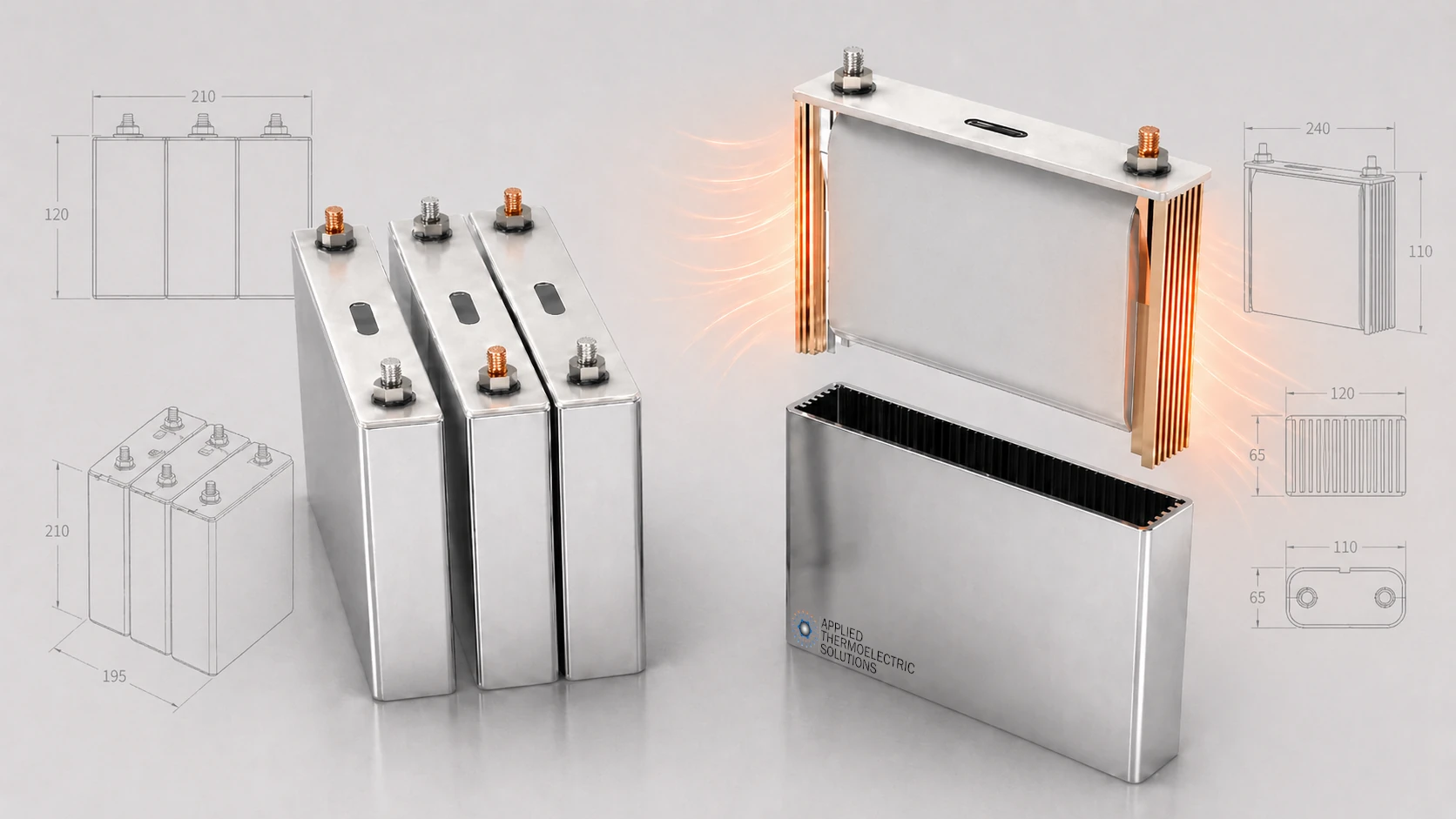
Battery Thermal Management From the Inside Out
Conventional battery thermal-management systems cool or heat the outside of a battery cell. ParaThermic® began with a different question: instead of continually improving the thermal-management system around the battery, what if the battery itself were redesigned to be easier to cool?
The reasoning is simple. No matter how advanced the external system becomes, heat must still travel through the battery’s internal materials before it reaches the cooled surface. More aggressive external cooling lowers the cell surface temperature but does not remove the internal thermal barrier. Instead, it increases the temperature gradient inside the cell, and those gradients accelerate battery degradation, increase cost, and reduce safety margin.
ParaThermic® High-Heat-Transfer (HHT) technology is a structural, non-chemical battery architecture that reduces the thermal resistance between the heat-generating regions inside a cell and its external thermal management system interface, making the battery easier to cool and to heat. With a modeled heat-removal rate up to 20× greater than a conventional battery, ParaThermic® has the potential to transform what batteries can do.
Peer-reviewed research found that the ParaThermic® architecture increased maximum heat-removal capability by:
- 10.3× with air cooling
- 13.7× with liquid cooling
- 20.7× with refrigerant cooling
These are apples-to-apples comparisons in which the external cooling method remained the same and the battery architecture changed.
The importance of these results is not the multiplier alone. It is what this level of internal heat transfer could enable:
- Thermal capability for a 3.5-minute full charge
- Fifteen-minute charging using lower-cost air cooling
- Rapid restoration of cold-weather battery power and charge acceptance
- Substantially longer battery life
- Lower thermal-management system energy consumption
- Smaller and lower-cost battery packs
- Higher-energy density and higher-capacity cell designs
- Fewer cells and simpler battery packs
- Faster response during high-power operation
- Potential to prevent early-stage thermal runaway escalation
2026 Create the Future Design Contest Grand Prize Finalist
ParaThermic® was selected as the Energy, Power & Propulsion finalist and one of seven Grand Prize finalists from more than 600 entries in the 2026 Create the Future Design Contest presented by Tech Briefs.
Explore ParaThermic®:
Why It Matters | How It Works | Evidence | Physical Validation | Manufacturing | Licensing | FAQ
See How ParaThermic® Changes Battery Heat Transfer
This overview illustrates the internal thermal bottleneck in conventional batteries and how ParaThermic® redesigns the battery’s internal heat-transfer pathway to support greater heat removal, faster thermal response, and improved temperature uniformity.
Current ParaThermic® Evidence and Development Status
ParaThermic® has progressed from concept into engineering and manufacturing development, supported by peer-reviewed thermal modeling, fabricated ThermalConnect® components, and production-oriented supplier work. The next major step is controlled cell-level physical validation.
Established Evidence
- Peer-reviewed HHT thermal analysis published in Applied Thermal Engineering
- Conventional-cell thermal model validated against published experimental and CFD results
- Issued U.S. patents covering aspects of the battery thermal architecture, including U.S. Patent Nos. 11,670,813 and 12,700,629
- Physical ThermalConnect® development components fabricated
- Supplier-level manufacturing drawings and tolerances developed for production-intent ThermalConnect® geometry
- Supplier evaluation of ThermalConnect® production at 100,000 and 1,000,000-piece quantities using established aluminum extrusion, cutting, and surface-treatment processes
Development Underway
- Generation 2 ThermalConnect® development to reduce mass and manufacturing complexity while improving robustness
- Electrical-isolation and dielectric-coating development
- Joining-process development and qualification
- Refinement of manufacturable cell geometry within the high-performing HHT design space
Next Major Validation
The next major step is maximum heat-transfer-rate testing of two battery architectures with the same active-material volume.
One test cell will use a conventional battery architecture and an aspect ratio representative of conventional thermal design. The second will use the ParaThermic® architecture with an aspect ratio developed specifically for the ParaThermic® architecture. Both will use the same underlying chemistry, materials, and electrode-layer construction so the comparison isolates the effect of battery architecture and geometry rather than differences in cell construction or thermal properties.
The initial testing will use electrically heated, non-energized test cells that reproduce the relevant internal thermal structure of each architecture. Electric heaters will simulate internal heat generation, and the cells can be constructed without electrolyte where appropriate. This approach is intended to reduce development risk, accelerate the test program, and resolve thermal-design issues before progressing to more costly and complex live electrochemical-cell testing.
The tests will determine the maximum heat-transfer rate each architecture can sustain under the same thermal limits and external boundary conditions. The resulting data will then help de-risk live-cell testing for cycling, degradation, durability, and abuse validation.
Why ParaThermic® Matters

Conventional Batteries Are Reaching the Internal Temperature-Gradient Limit
Battery thermal management has traditionally improved heat removal by increasing the external heat-transfer coefficient or reducing the cooled-surface temperature.
This has driven the progression from:
- Natural and forced-air cooling
- Liquid cold plates
- Direct refrigerant cooling
- Immersion cooling
- Mist cooling
- More aggressive flow rates and lower coolant temperatures
These methods can make the battery surface colder and transport more heat after it reaches the external interface. They do not automatically reduce the thermal resistance inside the battery.
Battery heat transfer can be represented by:
\dot{Q}_{\mathrm{battery}} = \frac{\Delta T_{\mathrm{battery}}} {R_{\mathrm{th,battery}}}
Where:
\dot{Q}_{\mathrm{battery}} is the heat-transfer rate.
\Delta T_{\mathrm{battery}} is the surface to battery center temperature difference driving the heat.
R_{\mathrm{th,battery}} is the internal battery thermal resistance.
Greater heat transfer through the same internal thermal resistance requires a larger internal temperature difference. Lowering internal thermal resistance changes that relationship.
USABC thermal-management goals call for less than 3°C cell-to-cell temperature variation across a pack and less than 3°C temperature variation across a cell surface. These are not core-to-surface limits, but they illustrate how tightly battery temperature uniformity is controlled.
Published experiments using internal temperature sensors have reported internal-to-surface temperature differences of approximately 5.5°C to 15°C in lithium-ion cells rejecting heat through their external surfaces, including up to 11.3°C in a commercial 37 Ah prismatic cell.
Separately, validated electrothermal-degradation research found that a through-thickness thermal gradient of only 3°C within the active region of a pouch cell accelerated degradation by 300% under the evaluated conditions.
These measurements are not identical to the USABC temperature-uniformity definitions, but together they show that conventional batteries can already develop internal gradients beyond the few-degree range in which temperature nonuniformity becomes important.
Once a conventional battery reaches its allowable internal temperature gradient, further lowering the surface temperature creates a tradeoff:
- More heat can be removed.
- Internal thermal stress increases.
- Current and impedance become less uniform.
- Localized degradation can accelerate.
- Usable capacity can become limited by the most affected regions.
- Safety margin can be reduced.
As the battery industry pushes toward more aggressive external cooling, the battery surface is driven colder relative to the interior, increasing the surface-to-center temperature difference. The resulting temperature gradients accelerate degradation, reduce safety margin, and increase cost because additional beginning-of-life capacity and power margin are required to compensate for temperature-gradient-driven degradation to meet end-of-life requirements.
ParaThermic® addresses the other side of the heat-transfer relationship by reducing \(R_{\mathrm{th,battery}}\). Lower internal thermal resistance allows more heat to be transferred at the same internal temperature difference, or the same heat to be transferred with a smaller temperature difference.
A Larger Thermal Advance Than Moving From Air to Liquid Cooling
The move from air cooling to liquid cooling represented an important improvement in battery thermal management.
For the conventional reference battery evaluated in the peer-reviewed ParaThermic® study, changing from air cooling to liquid cooling increased maximum heat removal from approximately 2.4 watts to 16.1 watts:
\frac{16.1\ \mathrm{W}}{2.4\ \mathrm{W}} = 6.7
That was a 6.7\times improvement.
ParaThermic® produced even larger gains while holding the external cooling method constant:
| Cooling Method | Conventional Battery | ParaThermic® Battery | Improvement |
|---|---|---|---|
| Air | 2.4 W | 24.8 W | 10.3× |
| Liquid | 16.1 W | 220.7 W | 13.7× |
| Refrigerant | 17.5 W | 362.3 W | 20.7× |
Maximum heat removal was defined using the same thermal limits for both architectures: either a 60°C battery-center temperature or a 20°C maximum internal temperature difference. The 20°C criterion represented an extreme condition for evaluating maximum heat-transfer capability rather than a recommended continuous operating target.
This comparison evaluates the complete ParaThermic® architecture, including the cell geometry developed around its intended heat-transfer path, against the conventional reference under the same external cooling method and thermal limits.
ParaThermic® with air cooling removed more heat than the conventional battery could remove with either liquid or refrigerant cooling.
The results show that ParaThermic® is not merely an incremental improvement to an external cooling system. It changes the internal battery resistance that limits how much benefit the external system can provide.
Thermal Capability for a 3.5-Minute Full Charge at 17C
Evidence: Peer-Reviewed ParaThermic® HHT Modeling, Applied Thermal Engineering (2025)
For the representative 25 Ah battery evaluated in the peer-reviewed research, the conventional battery reached its allowable center-temperature or internal-temperature-gradient limit at approximately 17.5 watts of heat removal, even with refrigerant cooling.
A 15-minute full-charge equivalent generated approximately 20 watts of heat. The conventional battery therefore could not thermally support even a 15-minute full charge using any of the evaluated air, liquid, or refrigerant cooling methods.
The optimized ParaThermic® configuration reached approximately 362 watts of heat removal with refrigerant cooling. That was sufficient to remove the calculated heat associated with a 3.5-minute full-charge equivalent, corresponding to an approximately 17C charging rate.
| Battery Configuration | Maximum Heat Removal |
|---|---|
| Conventional battery with refrigerant cooling | 17.5 W |
| Optimized ParaThermic® with refrigerant cooling | 362.3 W |
The difference is greater than twentyfold.
Fast-Charge Heat Does Not Increase Linearly
The thermal challenge of a 3.5-minute charge is much greater than the difference in charging time alone suggests.
Under the assumptions used in the peer-reviewed analysis:
| Full-Charge Time | Modeled Heat Generation |
|---|---|
| 15 minutes | 20 W |
| 10 minutes | 45 W |
| 5 minutes | 180 W |
| 3.5 minutes | 363 W |
The 3.5-minute charge produced an approximate heat-generation rate of:
- 18× the 15-minute charge
- 8× the 10-minute charge
- 2× the 5-minute charge
This nonlinear increase occurs because resistive battery heat generation varies approximately with the square of current. As charging time decreases, the required current rises, causing the rate at which heat must be removed to increase much faster than the reduction in charging time alone might suggest.
A 3.5-minute charge is therefore a much larger cooling challenge than it may initially appear. Reducing charge time from 15 minutes to 3.5 minutes is approximately a fourfold reduction in time, but the modeled resistive heat-generation rate increased by approximately 18×.
As charging rates increase, internal heat transfer becomes increasingly important because this rapidly increasing heat must be transferred from the battery interior to the cooling system without exceeding temperature or internal temperature-gradient limits.
ParaThermic® addresses this challenge by reducing the battery’s internal thermal resistance and increasing its heat-transfer capability.
Fifteen-Minute Charging With Air Cooling Where the Conventional Battery Fell Short With Refrigerant Cooling
Evidence: Peer-Reviewed ParaThermic® HHT Modeling, Applied Thermal Engineering (2025)
The optimized ParaThermic® battery could remove approximately 24.8 watts using air cooling. That exceeded the approximately 20-watt thermal load associated with a 15-minute full-charge equivalent.
The conventional battery could not meet that thermal load even with refrigerant cooling.
ParaThermic® met it with air.
This is more than a charging-speed result. It indicates that ParaThermic® may allow a simpler external thermal system to provide capability that otherwise requires a more complex system or cannot be achieved at all.
Compared with liquid or refrigerant systems, air cooling can avoid or reduce:
- Coolant and refrigerant
- Pumps and valves
- Cold plates and manifolds
- Liquid-to-air heat exchangers
- Plumbing and fittings
- Leak-management requirements
- Electrical-isolation concerns associated with liquids
- Maintenance and service requirements
- Thermal-system mass
- Packaging volume
- Thermal-management system cost
Air cooling has historically been limited by low heat-transport capacity and difficulty maintaining uniform battery temperatures.
ParaThermic® changes that tradeoff by reducing the resistance inside the battery rather than requiring the external air system to overcome the full internal resistance of a conventional cell.
Why ParaThermic® Is Expected to Improve Battery Life Beyond 3×

Evidence: Experimental battery cycling research and ParaThermic® thermal analysis
Experimental research at Imperial College demonstrated that changing the primary heat-flow direction from cross-plane surface cooling to in-plane tab cooling produced an equivalent 3× increase in battery pack life. After 1,000 cycles, the surface-cooled cells lost usable capacity under load at approximately three times the rate of the tab-cooled cells. The researchers attributed the difference to temperature gradients perpendicular to the battery layers, which produced nonuniform impedance, current distribution, and degradation.
ParaThermic® incorporates this same fundamental advantage, but it addresses additional thermal factors that the tab-cooling comparison did not.
ParaThermic® targets three major temperature-related degradation mechanisms:
- Reduced temperature differences between layers. ParaThermic® uses the battery’s higher-conductivity in-plane direction, addressing the same cross-plane gradient mechanism responsible for the threefold life difference in the Imperial study.
- Reduced temperature differences within the layers. ParaThermic® further reduces internal thermal resistance through architecture-specific geometry, shorter heat-flow distances, greater effective heat-transfer area, ThermalConnect® pathways, and reduced component and interface resistance.
- Less time at elevated temperature. Lower internal thermal resistance and faster thermal response allow heat to leave the battery more quickly, reducing thermal exposure during and after high-power operation.
The 3× life improvement demonstrated by in-plane cooling therefore represents only part of what ParaThermic® is designed to address. ParaThermic® also reduces within-layer temperature gradients and the time the battery spends at elevated temperature.
The technical expectation is therefore a battery-life improvement greater than 3×. Direct comparative cycling will establish the resulting improvement for the ParaThermic® architecture.
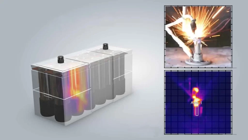
Potential to Prevent Early-Stage Escalation Into Full Thermal Runaway
Evidence: Peer-Reviewed ParaThermic® HHT Modeling, Applied Thermal Engineering (2025), and Internal Transient Modeling
Thermal runaway is a race between heat generation and heat removal. During onset, an abnormal condition produces self-heating. If heat removal exceeds heat generation, the cell can stabilize. Once heat generation exceeds heat removal and the reactions become self-sustaining, thermal management can no longer arrest the event.
Published onset-stage self-heating rates of 12–23°C/min, applied to the evaluated cell’s thermal capacitance of 624 J/°C, correspond to approximately 124–240 W of heat generation. Modeled ParaThermic® HHT heat-removal capability exceeded that range.
ParaThermic® also reduced the modeled thermal time constant from 1,186 seconds to 81 seconds, approximately 14.6× faster, allowing the thermal system to respond much earlier during the onset window.
Impact: The potential to remove abnormal heat before self-heating becomes self-sustaining and prevent escalation into full thermal runaway.
This capability does not apply to every failure mode. Severe penetration, hard internal shorts, crush damage, or already-developed thermal runaway can produce heat faster and more locally than the modeled thermal-management capability. Live-cell abuse testing will establish the actual intervention envelope.
Faster Thermal Response in Both Directions
Evidence: Peer-reviewed ParaThermic® HHT modeling, Applied Thermal Engineering (2025)
Reducing internal thermal resistance affects more than maximum heat-removal capability. It also allows the battery interior to respond more rapidly when heat is either removed from or added to the cell.
The modeled thermal time constants were:
| Configuration | Thermal Time Constant |
|---|---|
| Conventional battery | 1,186 seconds |
| ParaThermic® with conventional aspect ratio | 686 seconds |
| ParaThermic® with optimized aspect ratio | 81 seconds |
Even without changing the conventional aspect ratio, the ParaThermic® architecture reduced the modeled thermal time constant from 1,186 to 686 seconds, corresponding to approximately 1.7× faster thermal response.
Optimizing the cell geometry for the ParaThermic® heat-flow direction reduced the time constant much further, from 686 to 81 seconds, an additional improvement of approximately 8.5×. Compared with the conventional battery architecture, the optimized ParaThermic® configuration responded thermally approximately fifteen times faster.
During cooling, this allows internally generated heat to reach the external thermal-management interface more rapidly. During heating, it allows externally supplied heat to reach the battery interior more rapidly and uniformly.

Increased Cold-Weather Power and Range Through Rapid Battery Warm-Up: 6–46 Minutes Instead of 80
Evidence: Internal ParaThermic® thermal modeling
Warming a cold lithium-ion battery restores power, usable energy, charge acceptance, and regenerative-braking capability. The problem is that conventional batteries can take too long to warm for those benefits to be fully realized when the user needs them.
ParaThermic® changes that through much faster battery warm-up. It reduced modeled warm-up time from approximately 80 minutes for the conventional battery architecture to 6–46 minutes for the ParaThermic® configurations, while limiting the maximum internal temperature difference to 5°C. ParaThermic® increased heat transfer into the battery by approximately 1.7× to 13×, allowing heat to move through the battery faster and more uniformly.
For an electric vehicle, rapid battery preconditioning can begin remotely before departure, or the battery can continue warming rapidly after the vehicle starts moving. At these warm-up rates, the driver can recover battery power, usable range, regenerative braking, and charging capability soon enough for the improvement to be felt during normal use, rather than after much of the trip is already over.
The same advantage extends to other cold-weather battery applications, including aircraft, defense equipment, and outdoor energy storage, where power, energy, or charging capability needs to recover quickly after a cold soak.
Better Thermal Management Can Pay for Itself Through Battery Downsizing
Evidence: NREL thermal-management sizing analysis, independent degradation research, and ParaThermic® application-level sensitivity analysis
Battery packs are sized at the beginning of life so they can still meet required energy and power at the end of life. Temperature-gradient-driven degradation increases the beginning-of-life capacity and power margin required to meet those end-of-life requirements.
Reducing that degradation reduces the battery margin that has to be installed in the first place.
Based on the available degradation and thermal-management research, ParaThermic® supports evaluating a 5–20% reduction in required battery capacity or power margin.
For an illustrative 100-kWh battery, that corresponds to 5–20 kWh less installed battery capacity. At an illustrative cell cost of $100/kWh, that represents approximately $500–$2,000 in avoided cell cost, before considering additional reductions in battery mass, volume, structure, and associated pack hardware.
NREL demonstrated this economic mechanism in a Phoenix standby-cooling analysis. Improved thermal management reduced battery degradation, allowing the battery to be downsized in both beginning-of-life energy capacity and power capability. The resulting battery savings exceeded the added cost of the thermal-management system.
The mechanism is straightforward:
Lower temperature-gradient-driven degradation → less beginning-of-life battery margin → smaller battery → lower battery cost
For an illustrative 100-kWh application:
| Reduction in Required Installed Capacity | Avoided Capacity | Illustrative Cell Value at $100/kWh |
|---|---|---|
| 5% | 5 kWh | $500 |
| 10% | 10 kWh | $1,000 |
| 15% | 15 kWh | $1,500 |
| 20% | 20 kWh | $2,000 |
ParaThermic® is expected to provide a greater opportunity than an external-cooling-only improvement because it addresses average temperature, internal gradients, and thermal response together.
Lower Refrigeration Work as Heat Load Increases
Evidence: Internal ideal-cycle thermodynamic analysis using the published ParaThermic® HHT model
Reducing internal battery thermal resistance allows the same battery-center temperature to be maintained with a warmer cooling interface. For a vapor-compression cooling system, that reduces the required temperature lift, increases COP, and reduces refrigeration work.
For the evaluated conditions, with a battery-center temperature of 30°C and condenser temperature of 65°C, the calculated COP at a 50 W battery heat load was approximately 1.6 for the mathematically extended conventional-battery case, 2.8 for ParaThermic® with conventional aspect ratio, and 7.0 for ParaThermic® with optimized aspect ratio.
The refrigeration-work advantage increases with battery heat load because lower internal thermal resistance allows the cooling interface to remain progressively warmer while maintaining the same battery-center temperature.
| Battery Heat Generation | ParaThermic® with Conventional Aspect Ratio | ParaThermic® with Optimized Aspect Ratio |
|---|---|---|
| 5 W | 10% lower | 22% lower |
| 10 W | 17% lower | 36% lower |
| 20 W | 26% lower | 54% lower |
| 40 W | 38% lower | 72% lower |
| 50 W | 42% lower | 77% lower |
At 50 W, the optimized ParaThermic® configuration required approximately 77% less ideal refrigeration work than the mathematically extended conventional-battery case.
The published HHT analysis found that the conventional architecture reached its maximum refrigerant-cooled heat-removal capability at approximately 17.5 W, using the same thermal limits applied elsewhere in the study: a maximum battery-center temperature of 60°C or a maximum internal temperature difference of 20°C. The 20–50 W conventional values above therefore illustrate the refrigeration requirement obtained by mathematically extending the conventional architecture beyond its feasible modeled thermal range.
At lower heat loads, ParaThermic® reduces refrigeration work. At higher loads, the more important result is that ParaThermic® continues transferring heat after the conventional architecture has already reached its internal thermal limit.
These calculations represent ideal-cycle refrigeration performance. Actual system energy consumption depends on compressor, fan, pump, heat-exchanger, control, ambient, and operating conditions.
Why Lower Refrigeration Work Matters
Fast charging can place a large cooling demand on a vehicle while it is stationary and has no vehicle-generated airflow. A reported 2019 BMW technology search for fast-charging cooling called for proposed solutions capable of more than 20 kW of cooling during 200–300 kW charging, while limiting cooling-system noise to 35 dB(A) and providing the required heat rejection with the vehicle stationary. BMW fast-charging cooling technology search
Reducing refrigeration work directly reduces compressor power. It can also reduce the total heat that the condenser must reject because the compressor’s electrical work is added to the battery heat on the condenser side of the refrigeration cycle.
This creates opportunities for:
- Lower compressor, fan, and pump power
- Lower airflow or coolant-flow requirements
- Quieter operation through reduced compressor, fan, and pump demand
- Smaller or lighter heat exchangers and thermal-management hardware
- Lower auxiliary electrical demand
- Greater net system efficiency
The significance is not limited to passenger vehicles. In battery-powered vehicles and equipment, energy consumed by thermal management competes directly with energy available for propulsion or other useful work. During fast charging, lower auxiliary demand can also reduce the electrical and heat-rejection burden precisely when cooling requirements are highest.
Two Ways ParaThermic® Enables Higher Energy Density and Cell Capacity
Evidence: Peer-reviewed HHT analysis published in Applied Thermal Engineering and application-level engineering analysis
Increasing cell energy or capacity generally increases the thermal burden.
Higher-energy-density cells store and transfer more energy within a given cell volume. Because charging and discharging are not perfectly efficient, greater energy throughput produces greater heat generation. Higher-capacity cells also require greater current at the same C-rate, while increased electrode loading can add electrochemical and transport losses.
In the peer-reviewed HHT analysis, the representative conventional battery was already unable to thermally support a 15-minute full-charge heat load, even with refrigerant cooling.
Increasing energy or capacity without improving the internal thermal pathway can therefore result in:
- Higher internal temperature gradients
- Reduced safety margin
- Accelerated degradation
- Greater cooling-system requirements, cost, or performance derating
ParaThermic® can enable higher energy density and cell capacity through two fundamentally different mechanisms. One removes an internal thermal constraint on higher-energy designs. The other makes more of the existing cell envelope available for active material.
1. Removing the Internal Thermal Constraint
More aggressive external cooling lowers the cell surface temperature, but it does not remove the thermal resistance between the battery interior and that surface. Once the cell becomes internally gradient-limited, additional external cooling increases the internal temperature difference rather than eliminating the underlying thermal constraint.
ParaThermic® reduces that internal thermal resistance.
Lower internal thermal resistance allows a cell to move more heat while maintaining an acceptable internal temperature gradient. This can make higher-energy, higher-capacity, or more heavily loaded cell designs practical when their additional thermal burden would otherwise limit charging, power, life, or safety.
ParaThermic® does not create higher-energy chemistry. It can remove a thermal constraint that limits how effectively higher-energy chemistry, greater active-material loading, increased cell capacity, and higher sustained power can be used.
This creates potential pathways toward:
- Higher-capacity cells
- Higher active-material loading where electrochemically appropriate
- Higher-energy chemistries
- Greater sustained charge and discharge capability
- Less temperature-based performance derating
- Higher usable cell-level and pack-level energy density
2. Increasing the Space Available for Active Material
A conventional prismatic battery cannot devote its entire internal volume to electrochemically active material. Space is also required for current collectors and terminal connections, electrical isolation, electrolyte and filling requirements, assembly clearances, mechanical tolerances, and other functional structures.
ThermalConnect® can use regions that are already unavailable to active material in the conventional reference architecture. The ParaThermic® thermal pathway can therefore be incorporated without requiring a corresponding reduction in electrode volume.
A more compact ThermalConnect® implementation creates an additional opportunity. If the required thermal and electrical-isolation functions can be provided within a smaller portion of this inactive region, some of the recovered cell volume can be reassigned to the electrode assembly, increasing the amount of active material within the same external cell envelope.
Not all internal clearance can or should be eliminated. Electrical isolation, electrolyte access, terminal integration, manufacturing tolerances, mechanical behavior, venting, and safety requirements must still be preserved.
The first mechanism removes a thermal barrier to higher-energy cell designs. The second increases the opportunity to place more active material within the same cell envelope.
Thicker Cells Can Reduce Battery-Pack Part Count and Complexity
Evidence: Peer-reviewed ParaThermic® HHT modeling, Applied Thermal Engineering (2025)
Conventional battery thickness can be constrained by thermal management because increasing the distance heat must travel through the low-conductivity cross-plane direction increases internal thermal resistance and temperature gradients.
ParaThermic® changes that relationship. Increasing cell thickness can add active material and heat-transfer area without proportionally increasing the intended internal heat-flow distance.
A thicker cell does not require thicker individual electrode coatings. Additional capacity can instead come from more electrode layers and different cell proportions while maintaining electrode coating thicknesses appropriate for electrochemical performance.
This creates the opportunity to use fewer, higher-capacity cells to provide the same battery-pack capacity. The peer-reviewed ParaThermic® paper notes that fewer cells can reduce bus bars, connectors, welds, wires, fasteners, assembly time, and BMS complexity. At the pack level, fewer cells can also reduce sensing connections, cooling interfaces, retaining and interconnect hardware, joining operations, and other components associated with each individual cell.
Fewer cells can therefore translate the thermal and geometric advantages of ParaThermic® into a simpler, lighter, and less costly battery pack.
The optimum cell size remains a system-level design decision because fewer, larger cells also affect pack voltage and current, redundancy, fault tolerance, safety architecture, manufacturability, serviceability, and packaging.
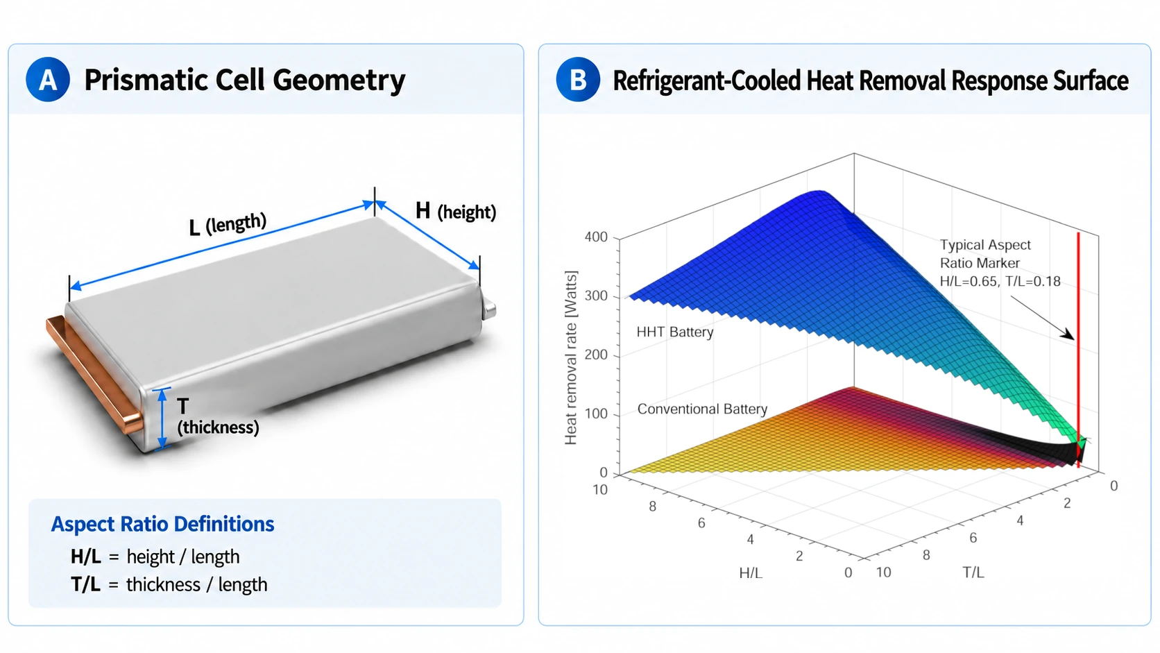
The Published Gains Reflect the Evaluated Design Space, Not a Demonstrated Ceiling
Evidence: Peer-reviewed ParaThermic® HHT modeling, Applied Thermal Engineering (2025)
The peer-reviewed ParaThermic® study evaluated a defined range of battery aspect ratios. The published maximum heat-removal improvements of 10.3× with air cooling, 13.7× with liquid cooling, and 20.7× with refrigerant cooling therefore represent the performance achieved within the geometries that were modeled.
For HHT batteries, maximum heat-removal capability continued to increase approximately linearly as H/L increased through the modeled range, which extended to approximately H/L = 10. The response had not reached a thermal maximum at the upper H/L boundary.
The study did not extend H/L indefinitely. The peer-reviewed paper notes that the manufacturability of these less conventional aspect ratios should be assessed and discusses approximately H/L = 10 in the context of existing manufacturing capability. It also notes that the additional thermal performance could provide an incentive for battery-manufacturing innovation.
The published ParaThermic® gains therefore represent the performance demonstrated within the evaluated geometry range, not a demonstrated upper performance limit of the architecture.
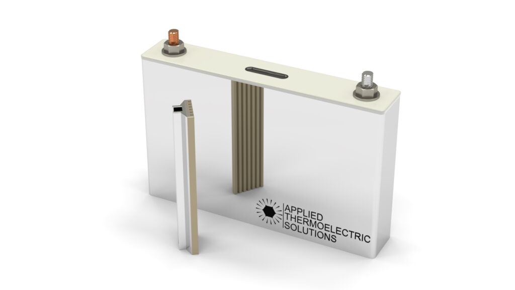
What Is ParaThermic®?
ParaThermic® is a low-internal-thermal-resistance battery architecture that creates more effective thermal pathways between heat-generating regions inside the cell and the intended external thermal-management interface.
It is not an external thermal-management technology such as:
- A new cooling fluid
- A cold plate
- A thermoelectric module
- An external heat spreader
It is also not a battery chemistry or a standalone battery thermal-management system.
It is a change to the battery architecture itself, including the internal thermal pathway and the cell geometry developed around that architecture.
ParaThermic® is designed to make whichever external cooling or heating system is selected more effective.
How ParaThermic® Works
This technical explanation shows why reducing internal battery thermal resistance requires more than applying cooling to a different cell surface. ParaThermic® combines the battery’s higher-conductivity heat-flow direction with optimized geometry, ThermalConnect® pathways, and reduced component and interface resistance.
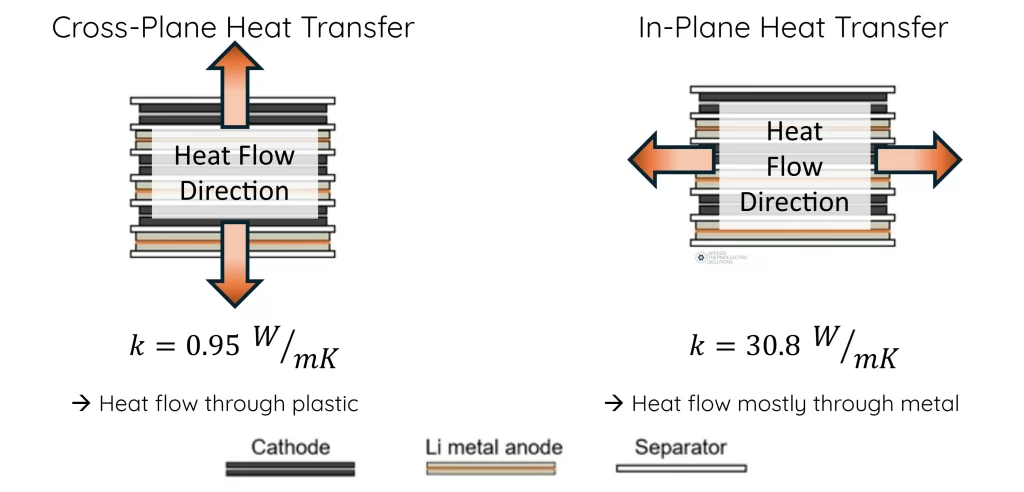
1. It Uses the Battery’s Higher-Conductivity In-Plane Direction
Lithium-ion cells contain layered electrode, separator, current-collector, and electrolyte structures.
These structures are thermally anisotropic.
Heat generally moves much more readily along the plane of the layers than through the thickness of the complete electrode stack.
The representative properties used in the peer-reviewed model included:
- In-plane thermal conductivity: 30.8 W/m·K
- Cross-plane thermal conductivity: 0.95 W/m·K
For those modeled properties, in-plane conductivity was more than thirty times higher. The exact thermal-conductivity anisotropy depends on the cell materials and layered construction rather than being a universal lithium-ion battery constant.
ParaThermic® directs heat toward the intended thermal-management interface using this higher-conductivity direction rather than relying primarily on heat flow through adjacent layers.
2. It Optimizes Cell Geometry for the Intended Heat-Flow Direction
Thermal resistance through a solid can be represented by:
R_{\mathrm{th}}=\frac{L}{kA}
Where:
L is the heat-flow distance.
k is the thermal conductivity in the selected direction.
A is the area normal to the direction of heat flow.
Thermal resistance decreases when:
Heat-flow distance is shortened.
Conductivity in the heat-flow direction increases.
Effective heat-transfer area increases.
ParaThermic® combines the battery’s higher in-plane thermal conductivity with geometry developed around that thermal path.
The dimensions, active area, heat-flow direction, thermal connections, case interface, and external thermal-management system are considered together rather than merely applying cooling to a different side of a conventional cell.
3. ThermalConnect® Extends the Internal Path to the Cell Interface
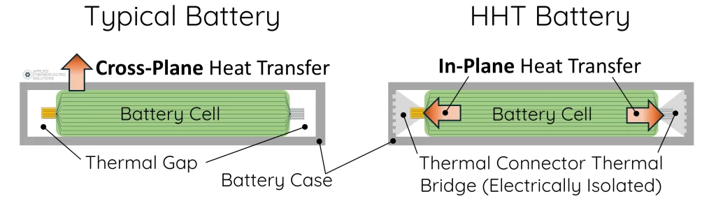
Using the battery’s higher-conductivity direction is not sufficient if heat reaches the end of the electrode structure and then encounters a high-resistance path before reaching the case or external thermal-management system.
ThermalConnect® provides dedicated thermally conductive pathways from multiple internal battery regions toward the intended cell thermal-management interface.
These pathways extend the favorable internal heat-flow direction beyond the electrode structure so heat can be transferred efficiently toward the cell case and external thermal-management system.
ThermalConnect® is one of the elements that distinguishes ParaThermic® from basic edge or tab cooling because it extends the internal thermal pathway rather than relying only on the existing cell edge or electrical terminals.
4. Low-Resistance Interfaces Preserve the Internal Thermal Path
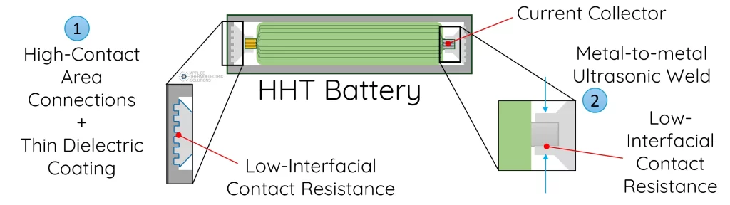
A high-conductivity component alone does not guarantee a low-resistance thermal system. Heat must also cross the connections between components without losing the advantage created by the ParaThermic® geometry and internal heat-transfer path.
ParaThermic® addresses two critical interfaces.
Current collector to ThermalConnect®. The design calls for a direct metallurgical connection between the current-collector structure and ThermalConnect®. Ultrasonic welding is the joining approach currently being developed and qualified because it can provide a low-resistance thermal connection using an established high-volume battery-manufacturing process.
ThermalConnect® to cell case. ThermalConnect® uses a large-area interface with the cell case to reduce thermal interface resistance. An electrically insulating, thermally conductive layer maintains the required isolation between the electrically connected ThermalConnect® structure and the case while preserving a low-resistance path for heat.
Together, these interfaces help preserve the low thermal resistance created inside the battery all the way from the heat-generating electrode structure to the external thermal-management interface.
Heat Continues to Flow Through Every Available Path
ParaThermic® does not force all battery heat through a single new route. Heat continues to distribute through every available path according to the thermal resistance of those paths and the temperature differences driving them.
ParaThermic® changes that resistance network by creating more direct, lower-resistance pathways toward the intended thermal-management interface. The existing heat-flow paths remain available, but a greater portion of the generated heat follows the lower-resistance ParaThermic® pathways.
The result is greater heat transfer for a given internal temperature difference, without requiring all heat to follow one prescribed path.
ParaThermic® Goes Beyond Tab and Edge Cooling
Evidence: Peer-reviewed battery thermal-management research and peer-reviewed ParaThermic® HHT modeling
Previous pouch-cell research has quantified important benefits of using the higher-conductivity in-plane direction of layered battery materials. Imperial College demonstrated that tab cooling can greatly improve internal temperature uniformity and, using 80% capacity as the automotive end-of-life criterion, concluded that tab cooling rather than surface cooling was equivalent to extending battery-pack lifetime by 3× under the evaluated conditions. Hunt et al. 2016
Later research showed both the benefits and the limitations of applying that principle through conventional battery tabs. Zhao et al. identified a thermal bottleneck between the electrode stack and the tabs and showed that changes in tab position, width, thickness, and connection resistance could improve heat rejection while retaining the temperature-uniformity advantages of tab cooling. Hales et al. subsequently found that tab cross-sectional area remained a significant bottleneck: increasing tab thickness by 34% improved tab-cooling performance by 20% with only a 0.7% reduction in specific energy. These studies showed that cell design itself can be changed to better exploit in-plane heat transfer. Zhao et al. 2019 Hales et al. 2020
Edge cooling uses the same favorable in-plane direction by applying the cooling boundary to the edge of an existing cell. The battery architecture itself remains unchanged. The cell geometry, internal heat-flow distances, internal connections, and interfaces are not redesigned around that thermal path. Published edge-cooling research
ParaThermic® research addresses a broader thermal-design objective. It incorporates the established benefits of in-plane heat transfer, but goes beyond improving temperature uniformity or optimizing the tabs of a conventional electrode stack. The peer-reviewed HHT research showed that the cell aspect ratio should be designed for the intended heat-flow direction and that heat-flow distance, component resistance, and interface resistance must be addressed as part of the complete internal thermal path. Piggott et al. 2025
Within the evaluated design space, ParaThermic® increased modeled maximum heat removal by 10.3× with air cooling, 13.7× with liquid cooling, and 20.7× with refrigerant cooling compared with the conventional battery architecture. Piggott et al. 2025
The scale of the difference is significant: Zhao et al. showed that optimized tab cooling could bring heat removal approximately to parity with surface cooling while improving temperature uniformity. Hales et al. demonstrated a 20% improvement in tab-cooling performance through increased tab thickness. ParaThermic® produced modeled increases of 10.3× to 20.7× in maximum heat-removal capability by redesigning the battery architecture around the thermal path.
The patented ParaThermic® architecture achieves this by combining the favorable in-plane direction with architecture-specific cell geometry, shorter internal heat-flow distances, greater effective heat-transfer area, ThermalConnect® pathways from multiple internal regions, and low-resistance interfaces. The architecture then carries that thermal path through low-resistance internal joining, large-area electrically isolated case interfaces, and integration with the intended external thermal-management surface.
Prior tab- and edge-cooling research provides independent evidence for the benefits of in-plane heat transfer. ParaThermic® incorporates those established physical principles into an architecture designed to expand whole-cell heat-transfer capability. The complete battery architecture is designed around that objective so the rest of the thermal path does not become the new bottleneck.
Compatible With Multiple Cooling and Heating Methods
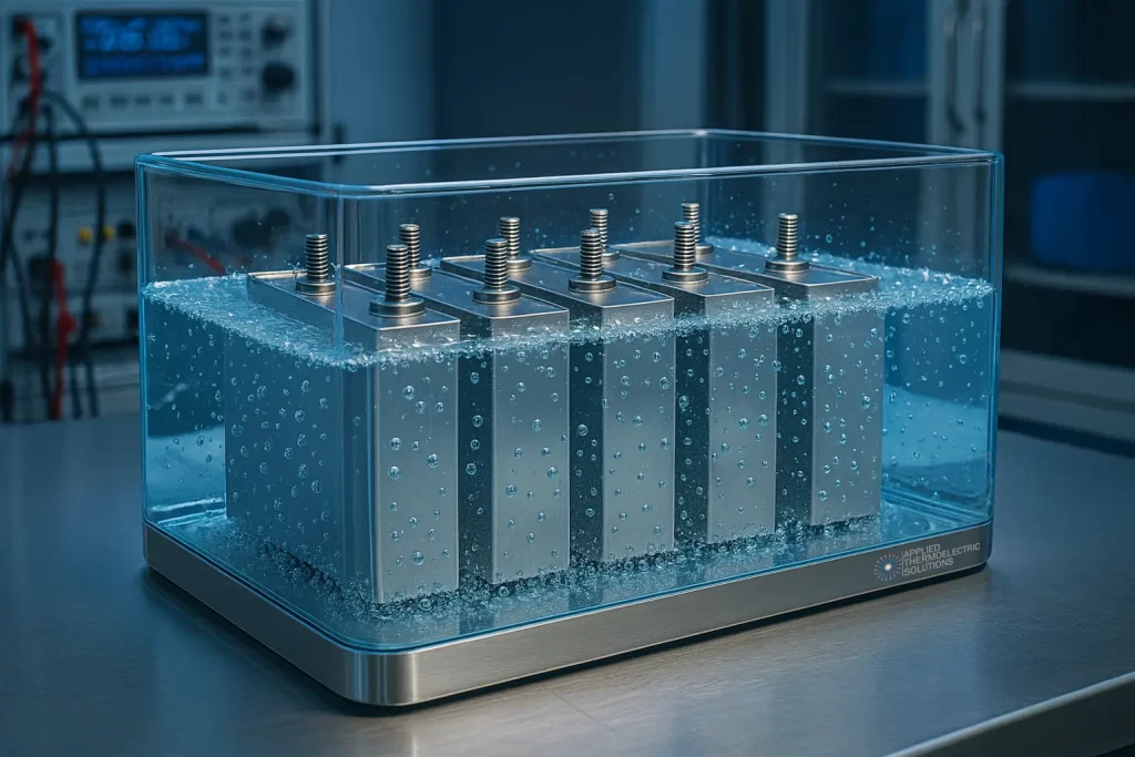
ParaThermic® is designed to work with a wide range of external thermal-management technologies. It can be used with:
- Air cooling
- Liquid cold plates
- Direct refrigerant cooling
- Immersion cooling
- Heat pipes and pumped two-phase systems
- Thermoelectric cooling and heating
- Hybrid thermal-management systems
It does not require thermoelectric cooling or any other specific external thermal-management technology.
Even highly capable external approaches such as immersion cooling primarily improve heat transfer at the cell boundary. They do not reduce the internal thermal resistance that heat must cross before reaching that boundary.
The external thermal-management system determines how heat is removed from or supplied to the cell at its thermal interface. ParaThermic® determines how effectively heat moves between that interface and the battery interior.
ParaThermic® Evidence Base and Validation
The ParaThermic® performance results presented on this page draw from several levels of evidence: peer-reviewed HHT modeling, additional ParaThermic® engineering analysis, directly related experimental battery research, and independent studies of battery degradation and system-level thermal effects.
The peer-reviewed HHT analysis was published in Applied Thermal Engineering in 2025 (DOI: https://doi.org/10.1016/j.applthermaleng.2025.126347). The study was authored by Alfred J. Piggott of Applied Thermoelectric Solutions; Jeffrey S. Allen of Michigan Technological University; and Ahmad A. Pesaran, whose affiliation in the published paper was the National Renewable Energy Laboratory (NREL).
Alfred J. Piggott, inventor of the ParaThermic® architecture and Founder and CTO of Applied Thermoelectric Solutions, has more than 30 years of engineering experience spanning battery thermal management, thermoelectrics, thermal modeling, mass-production automotive product design and development, patented thermal technologies, and peer-reviewed research.
Jeffrey S. Allen is the John F. and Joan M. Calder Endowed Professor in Mechanical Engineering-Engineering Mechanics at Michigan Tech, with expertise in interfacial transport phenomena, phase-change heat transfer, and thermal and mass transport.
Ahmad A. Pesaran, now Chief Energy Storage Engineer at the National Laboratory of the Rockies (NLR), has more than 25 years of recognized work in battery thermal management, thermal characterization, calorimetry, electrochemical-thermal modeling, and battery safety. He previously managed the laboratory’s energy-storage research team and has worked with automotive and battery manufacturers on battery thermal-analysis and thermal-management problems.
Before the model was used to predict HHT performance, the conventional-cell model was validated against published experimental measurements and separately benchmarked against published CFD.
| Validation Comparison | Difference | Error |
|---|---|---|
| Surface temperature vs. experiment | 0.7°C | 1.9% |
| Surface temperature vs. published CFD | 1.2°C | 3.2% |
| Center temperature vs. published CFD | 3.8°C | 9.2% |
The peer-reviewed study then used that validated conventional-cell framework to evaluate the HHT architecture. Depending on geometry and cooling conditions, the modeled heat-removal improvement was 10.3× with air cooling, 13.7× with liquid cooling, and 20.7× with refrigerant cooling.
Additional ParaThermic® engineering analyses extend the peer-reviewed modeling framework to other operating conditions and application questions, including cold-temperature warm-up, early-stage thermal-runaway response, BTMS energy requirements, and additional geometry studies. These analyses have not undergone the same independent peer-review process as the published HHT study and should be interpreted accordingly.
Independent published experimental and electrothermal research provides supporting evidence for the underlying relationships between heat-flow direction, internal temperature gradients, degradation, electrochemical behavior, and battery performance. Separate pack-level studies provide evidence for the effects of thermal conditions on battery sizing, usable energy, degradation, cooling requirements, and cost.
Controlled testing of assembled ParaThermic® cells remains the next major system-level validation step.
Taken together, the current evidence establishes the modeled thermal advantage of the HHT architecture, validates the conventional-cell modeling foundation used for the comparison, and independently supports the physical mechanisms and system-level relationships ParaThermic® is designed to address.
Potential ParaThermic® Applications
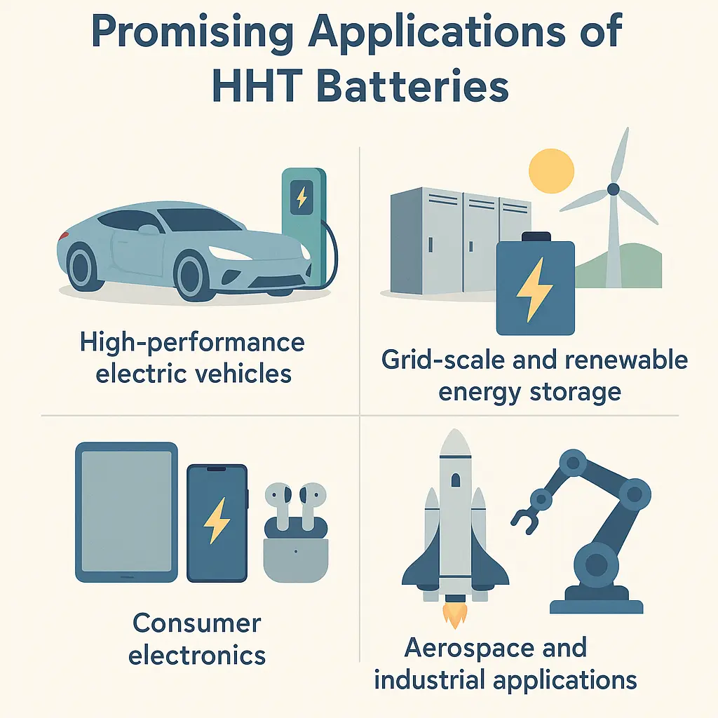
ParaThermic® can be applied wherever battery performance is limited by internal heat transfer, temperature gradients, thermal response, or the size and complexity of the external thermal-management system.
Passenger Electric Vehicles and Fast Charging
Passenger EVs can benefit from higher fast-charge thermal capability, rapid cold-weather preconditioning, longer battery life, reduced battery margin, and lower thermal-management energy and system cost. ParaThermic® is particularly relevant where increasingly capable external cooling is approaching the thermal limits of the cell itself.
Commercial Vehicles, Rail, and Off-Road Equipment
High-utilization batteries may experience repeated fast charging, long operating hours, sustained thermal loads, and wide ambient-temperature ranges. Faster thermal response, reduced temperature-gradient-driven degradation, and lower internal thermal resistance can support longer service life and faster return to operation. ParaThermic® is particularly relevant where thermal recovery time or repeated high-load operation limits equipment availability.
Aircraft, eVTOL, Drones, and Space Systems
In aerospace applications, thermal-management mass and energy consumption can be as important as thermal performance itself. One recent peer-reviewed eVTOL mission-level study found that thermal-management energy reached nearly 23% of total mission energy in the modeled hot-summer case, illustrating how strongly thermal management can affect the overall aircraft energy budget under demanding conditions.
Nakayama et al., “Mission-level integrated electrical–thermal simulation for energy and thermal management of eVTOL aircraft,” Applied Thermal Engineering (2026)
Increasing the battery’s internal heat-transfer capability can reduce the burden placed on the external cooling system and, where requirements permit a simpler or more efficient cooling architecture, create opportunities to reduce thermal-management power, pumps, coolant, plumbing, cold plates, heat exchangers, and other hardware. These reductions can be particularly valuable where thermal-management energy and every kilogram directly affect payload, range, or endurance.
Stationary, Industrial, and Specialized Battery Systems
Grid storage, UPS, telecom, robotics, marine, defense, medical devices, portable electronics, and power tools may benefit where operation is constrained by hotspots, temperature nonuniformity, sustained power, cold-weather performance, limited cooling area, or long service-life requirements. ParaThermic® is particularly relevant where increasing external cooling capacity alone does not adequately address the thermal limitation inside the cell.
View related battery and advanced thermal-management projects.
Manufacturing and Commercial Integration
ParaThermic® development has progressed beyond conceptual manufacturing analysis.
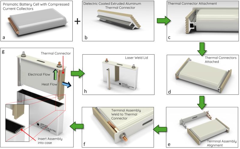
Physical ThermalConnect® development components have been fabricated, and production-intent geometry has progressed to supplier-level manufacturing drawings and tolerances.
A supplier has evaluated ThermalConnect® production at both 100,000 and 1,000,000-piece quantities using established aluminum extrusion, cutting, and surface-treatment processes. The evaluated production approach uses 6061-T6 aluminum with an appropriate electrically insulating thermal surface treatment.
This does not establish the cost, yield, or manufacturability of a complete production ParaThermic® battery. It demonstrates that a key novel component has progressed beyond conceptual geometry into a manufacturing approach based on established high-volume processes.

Commercial cell development must evaluate:
- Electrical isolation
- Coating integrity
- Thermal-interface resistance
- Joining quality
- Dimensional tolerance
- Mechanical durability
- Electrolyte compatibility
- Case integration
- Cell sealing
- Production inspection
- Manufacturing yield
- Cost at volume
- Recycling and service requirements
The objective is not simply to add a conductive component.
The complete cell must preserve electrochemical, electrical, mechanical, manufacturing, and safety functions while achieving the intended thermal performance.
Development, Modeling, and Validation
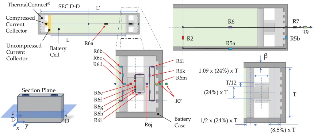
ParaThermic® can be adapted within an existing cell envelope, but the greatest design freedom and performance potential occur when the cell geometry, ThermalConnect® pathways, case interface, electrode configuration, and external thermal-management system are developed together.
Development Has Focused First on the Highest-Risk New Elements
ParaThermic® development has deliberately focused on addressing the highest-risk novel implementation questions before committing to complete custom-cell fabrication.
Work completed or underway includes ThermalConnect® geometry, electrical isolation, component fabrication, manufacturing methods, joining strategy, production scalability, and manufacturable cell geometry. In parallel, the underlying heat-transfer architecture has been modeled, compared with published experimental and CFD results, and peer reviewed.
This staged approach reduces the number of unresolved thermal and manufacturing questions carried into a complete live-cell build.
The next major system-level question is direct and measurable:
How closely will a physically assembled ParaThermic® architecture reproduce the predicted reduction in thermal resistance, internal temperature gradients, transient response, and increase in maximum heat-removal capability?
Same Active-Material Volume, Two Battery Architectures
The primary physical comparison will use two battery architectures with the same active-material volume.
The conventional test cell will use an aspect ratio representative of the 25 Ah prismatic geometry evaluated in the peer-reviewed HHT study, providing continuity with the conventional architecture used in the published modeling. The ParaThermic® test cell will use an aspect ratio developed specifically for the ParaThermic® heat-flow direction.
Both configurations will use the same underlying chemistry, materials, and electrode-layer construction so that the comparison isolates the effects of battery architecture and geometry, rather than differences in cell chemistry or thermal properties.
The repeating electrode-layer construction will remain matched, including electrode formulation and coating thickness, current-collector materials and thicknesses, separator construction, and other relevant layer properties. The number of repeated layers does not necessarily have to remain identical because changing cell geometry is itself part of the ParaThermic® architecture.
Cell geometry and the internal thermal pathway are coupled. Changing the intended heat-flow direction changes which dimensions control heat-flow distance and which dimensions create useful heat-transfer area. For that reason, forcing both architectures into the same cell proportions would prevent the comparison from testing one of the central ParaThermic® design principles.
The two architectures will be evaluated using equivalent heat generation, thermal limits, external thermal boundary conditions, and measurement methods.
The primary comparison therefore asks: how much thermal performance can be gained when the same amount of active battery material is configured around two different thermal architectures?
A Drop-In-Compatible ParaThermic® Path
A separate ParaThermic® development path can be evaluated for battery programs where retaining existing cell and pack interfaces is particularly valuable.
A drop-in-compatible configuration can preserve key external characteristics such as the cell envelope, nominal voltage and capacity, terminal locations, and pack electrical and mechanical interfaces while redesigning the internal electrode assembly and ThermalConnect® architecture for improved heat transfer.
This answers a different commercial question from the primary architecture comparison:
How much ParaThermic® performance can be obtained while preserving compatibility with an existing battery platform?
For programs where cell geometry can change, the fully integrated architecture provides the greatest design freedom and performance potential. For programs where packaging, qualification investment, platform compatibility, or development schedule dominate, the drop-in-compatible path provides a lower-integration-threshold route to ParaThermic®.
These are two development paths rather than better and worse versions of the same design. One uses greater design freedom to pursue the full ParaThermic® performance opportunity. The other improves internal heat transfer while preserving compatibility with an existing battery platform.
Controlled Thermal Testing Comes Before Live-Cell Testing
Initial physical validation will use electrically heated, non-energized test cells that reproduce the relevant layered thermal structure of the conventional and ParaThermic® architectures.
Electric heaters will provide controlled internal heat generation. Electrolyte can be omitted where appropriate because the purpose of this stage is to characterize the thermal architecture rather than electrochemical performance.
This approach allows heat input to be set directly and repeatedly instead of being inferred from electrochemical behavior. Differences between the configurations can therefore be attributed more cleanly to the thermal architecture rather than to cell-to-cell variation, aging, state of charge, or electrochemical differences.
The effective anisotropic thermal properties of the prototype stacks should also be characterized, either directly or from verified layer properties, so that the physical comparison and corresponding models use the thermal properties of the structures actually being tested. In-plane and cross-plane thermal conductivity are particularly important because their ratio depends on cell construction.
Initial testing is intended to measure:
- Maximum sustainable heat generation or heat-removal rate
- Internal thermal resistance
- Center and surface temperatures
- Layer-to-layer and within-layer temperature gradients
- Thermal time constant and transient response
- Spatial temperature distribution
The objective of this stage is to reduce development risk, accelerate the test program, and resolve thermal-design and manufacturing issues before progressing to more costly and complex live electrochemical-cell testing.
Live-Cell Validation Follows Thermal-Architecture Validation
Once the thermal architecture has been characterized, live electrochemical cells can address the questions that only live-cell testing can answer, including:
- Fast-charge behavior
- Charge acceptance
- Electrical performance
- Cycle life
- Degradation
- Durability
- Abuse and safety response
Model first. Validate the thermal architecture second. Live electrochemistry third.
Industry and SBIR/STTR Collaboration Opportunities
ParaThermic® is advancing toward cell-level prototype development, comparative testing, manufacturing integration, and application-specific validation.
Applied Thermoelectric Solutions welcomes collaboration with battery-cell manufacturers, vehicle and system OEMs, battery-pack and thermal-management developers, testing organizations, universities, and national laboratories.
Participation can range from a nonbinding expression of technical interest or an SBIR/STTR support letter to funded research, independent validation, prototype testing, or a joint demonstration program.
Potential collaboration can include:
- Application requirements and technical review
- Representative cells, materials, operating data, or manufacturing requirements
- Letters of support for qualified SBIR/STTR proposals
- Prototype fabrication, testing, and independent validation
- Joint research, development, and demonstration programs
Technology Licensing and Commercialization
ParaThermic® is available for commercial licensing and integration into battery-cell and battery-system platforms.
A useful first question is whether internal battery thermal resistance is limiting the performance of the application. Applied Thermoelectric Solutions can use application-specific modeling and engineering analysis to determine whether reducing that resistance creates sufficient value in heat-transfer capability, temperature uniformity, charging, battery life, thermal-management energy, or system cost to justify adoption.
The level of integration can vary with the application. Two implementation paths can be evaluated:
Fully integrated ParaThermic® architecture
The cell and thermal architecture are developed together to provide the greatest design freedom and performance potential.
Drop-in-compatible ParaThermic® architecture
Key external cell and pack interfaces are retained while the internal architecture is redesigned for improved heat transfer, reducing the integration threshold for existing platforms.
A commercial program can progress from feasibility analysis and application-specific modeling through prototype development, validation, manufacturing integration, and technology licensing.
Evaluate ParaThermic® for Your Battery System
ParaThermic® treats the battery’s internal architecture as part of the complete thermal-management system.
Based on peer-reviewed and internal modeling, reducing internal thermal resistance and designing the cell around the intended heat-flow direction can:
- Increase maximum heat-removal capability by 10.3× to 20.7×
- Support the thermal requirements associated with a 3.5-minute full-charge equivalent
- Reduce modeled warm-up from approximately 80 minutes to 6–46 minutes
- Reduce internal temperature gradients associated with degradation and thermal stress
- Improve thermal response by approximately fifteen times
- Reduce the burden placed on the external thermal-management system, creating opportunities for lower thermal-management energy, reduced battery margin, and simpler system designs
The result is not simply a different cooling method. It is a battery architecture designed to interact more effectively with whichever cooling or heating system is selected.
Applied Thermoelectric Solutions can evaluate whether internal battery thermal resistance is limiting your application and whether reducing that resistance creates sufficient performance or system-level value to justify a fully integrated or drop-in-compatible ParaThermic® architecture.
Frequently Asked ParaThermic® Battery Architecture Questions
What is a ParaThermic® battery?
ParaThermic® is a patented low-internal-thermal-resistance battery architecture. It redesigns the internal thermal pathway and cell geometry so heat can move more effectively between heat-generating regions inside the battery and the intended external thermal-management interface. It does not require a new battery chemistry or a particular external cooling technology.
Is ParaThermic® a cooling system?
No. ParaThermic® changes the battery architecture itself. The external thermal-management system still determines how heat is ultimately rejected or supplied. ParaThermic® reduces the internal thermal resistance between that system and the battery interior.
Why should battery developers care about internal thermal resistance?
Internally generated heat must cross the battery’s internal thermal resistance before it reaches the cooling system.
For a given internal thermal resistance, greater heat transfer requires a larger internal temperature difference. Reducing that resistance allows more heat to be transferred at the same temperature difference, or the same heat to be transferred with a smaller temperature difference.
Are conventional batteries already reaching their temperature-gradient limits?
Published experiments using internal temperature sensors have reported internal-to-surface temperature differences of approximately 5.5°C to 15°C in lithium-ion cells rejecting heat through their external surfaces, including up to 11.3°C in a commercial 37 Ah prismatic cell.
USABC thermal-management goals separately call for less than 3°C cell-to-cell temperature variation across a pack and less than 3°C across a cell surface. Those are not core-to-surface limits, but they illustrate how tightly battery temperature uniformity is controlled.
How Does Internal Thermal Resistance Limit More Aggressive Battery Cooling?
More aggressive external cooling can remove more heat from the cell surface, but it does not reduce the thermal resistance inside the battery. Heat generated in the battery interior must still cross that resistance to reach the cooled surface.
Greater heat transfer through the same internal thermal resistance requires a larger temperature difference between the battery interior and the surface. As cooling demands increase, these internal temperature gradients can accelerate degradation, increase thermal stress, and reduce safety margin.
ParaThermic® addresses this limitation by reducing the battery’s internal thermal resistance, allowing more heat to be transferred at the same internal temperature difference, or the same heat to be transferred with a smaller temperature difference.
What do the 10.3× to 20.7× heat-removal results mean?
In the peer-reviewed ParaThermic® HHT model, the external cooling method was held the same while the battery architecture was changed.
Under the same thermal limits, maximum modeled heat-removal capability increased by:
- 10.3× with air cooling
- 13.7× with liquid cooling
- 20.7× with refrigerant cooling
Maximum heat removal was defined using the same limits for both architectures: either a 60°C battery-center temperature or a 20°C maximum internal temperature difference. These are thermal heat-removal results, not electrochemical charging-rate guarantees.
What does the 3.5-minute result mean?
The model demonstrated the thermal capability to remove the heat associated with a 3.5-minute full-charge equivalent under the evaluated conditions.
It does not mean that an electrochemical cell has already been demonstrated charging from empty to full in 3.5 minutes. Actual charging capability also depends on chemistry, electrochemical kinetics, cell design, charging strategy, and other limits.
The modeled resistive heat-generation rate for the 3.5-minute case was approximately 18× that of the 15-minute case, illustrating how quickly the thermal challenge increases as charging time decreases.
Could ParaThermic® support fast charging with air cooling?
The peer-reviewed modeling showed that the ParaThermic® architecture could remove the modeled thermal load associated with a 15-minute full-charge equivalent using air cooling under the evaluated conditions.
That is a thermal capability result. Electrochemical charging performance must be established with live cells.
How much faster can a ParaThermic® battery warm up?
Internal modeling predicted approximately 6–46 minutes to warm from -20°C to 20°C for the evaluated ParaThermic® configurations, compared with approximately 80 minutes for the conventional battery architecture, while limiting the maximum internal temperature difference to 5°C.
Why do internal temperature gradients affect battery life?
Temperature differences inside a battery create nonuniform reaction rates, impedance, current distribution, and degradation.
Validated electrothermal-degradation research found that a 3°C through-thickness thermal gradient within the active region accelerated degradation by 300% under the evaluated conditions. Separate Imperial College cycling experiments showed that changing from surface cooling to tab cooling substantially improved battery life by reducing damaging through-thickness gradients.
Does ParaThermic® provide more than three times longer life?
Direct ParaThermic® cycling has not yet established a greater-than-3× life result.
Imperial College experimentally concluded that, for automotive applications using 80% capacity as the end-of-life criterion, tab cooling rather than surface cooling was equivalent to extending battery-pack lifetime by 3× under the evaluated conditions.
ParaThermic® incorporates the same favorable in-plane heat-transfer principle while also reducing total internal thermal resistance, within-layer temperature differences, and thermal response time. Greater than 3× is therefore a technically grounded expectation that direct comparative cycling will test.
Can ParaThermic® reduce battery-pack size and weight?
Potentially. Battery packs require beginning-of-life capacity and power margin so they can still meet requirements after degradation.
Reducing temperature-gradient-driven degradation can reduce the amount of margin that must be installed. Application-level sensitivity analysis supports evaluating approximately 5–20% battery reduction, depending on the application and degradation requirements. This is a design range to evaluate, not a universal battery-oversizing percentage.
Can better thermal management really reduce battery cost more than it adds?
Yes, under some conditions. NREL has demonstrated the underlying economic mechanism: improved thermal management reduced degradation and power fade enough to permit lower beginning-of-life battery sizing, and the battery savings exceeded the added thermal-management cost in the evaluated case.
For ParaThermic®, the economic question is application-specific: does reducing degradation, battery margin, and thermal-system burden create more value than the architecture adds?
Can ParaThermic® lower battery thermal-management energy?
Yes. Internal ideal-cycle analysis using the published HHT model found that reducing battery internal thermal resistance can allow a warmer cooling interface, reducing refrigeration temperature lift and required compressor work.
At a 50 W battery heat load, the optimized ParaThermic® case required approximately 77% less ideal refrigeration work than the mathematically extended conventional-battery case. The conventional architecture had already reached its modeled refrigerant-cooled thermal limit at approximately 17.5 W under the study’s thermal limits.
Actual system-level energy savings depend on compressor, fan, pump, heat-exchanger, controls, ambient conditions, and operating conditions.
Can ParaThermic® improve driving range or operating time?
Potentially. Energy consumed by compressors, pumps, fans, heaters, and other thermal-management hardware is energy that is unavailable for propulsion or useful work.
Reducing that auxiliary load can increase net usable energy. Battery downsizing and simpler or lighter thermal-management hardware can provide additional system-level benefits. The actual improvement in vehicle range or operating time must be evaluated for the specific application.
Can ParaThermic® enable higher-energy-density batteries?
Potentially. ParaThermic® does not increase the intrinsic specific energy of the battery chemistry.
It can improve application-level energy density if better thermal performance allows reduced battery margin, fewer cells, simpler thermal-management hardware, or more efficient use of available package volume and mass.
Can thicker cells improve electrochemical performance?
Conventional cell thickness can be thermally constrained because increasing the distance heat must travel through the low-conductivity cross-plane direction increases internal thermal resistance.
ParaThermic® changes that relationship by designing the geometry around the intended heat-flow direction. Higher cell capacity can come from more electrode layers and different cell proportions without requiring thicker individual electrode coatings.
This can create opportunities for fewer, higher-capacity cells and reduced pack-level component count.
Can ParaThermic® prevent thermal runaway?
ParaThermic® has the potential to prevent some early-stage abnormal heating events from escalating into full thermal runaway if heat can be removed faster than the cell is generating it during the onset period.
Modeling showed HHT heat-removal capability exceeding published onset-stage self-heating rates and a much faster thermal response than the conventional architecture.
ParaThermic® cannot be assumed to arrest severe penetration, crush damage, hard internal shorts, or thermal runaway that has already become self-sustaining. Live-cell abuse testing is required to establish the actual intervention envelope.
Does ParaThermic® require thermoelectric cooling?
No. ParaThermic® is designed to work with a range of external thermal-management technologies, including air cooling, liquid cold plates, direct refrigerant cooling, immersion cooling, heat pipes, two-phase systems, thermoelectric heating and cooling, and hybrid systems.
How is ParaThermic® different from edge or tab cooling?
Tab and edge cooling provide independent evidence for the benefits of moving heat along the higher-conductivity in-plane direction, but they do not constitute the ParaThermic® architecture.
Imperial College research found that tab cooling could provide much better thermal uniformity and was equivalent to 3× longer battery-pack life than surface cooling under the evaluated end-of-life criterion. Zhao et al. later showed that optimized tab cooling could bring heat rejection approximately to parity with surface cooling while retaining better uniformity. Hales et al. found that increasing tab thickness by 34% improved tab-cooling performance by 20%.
ParaThermic® addresses a broader objective. It redesigns the cell aspect ratio, heat-flow distance, effective heat-transfer area, internal pathways, component resistance, and interface resistance around the intended thermal path. The resulting peer-reviewed model produced 10.3× to 20.7× greater maximum heat-removal capability than the conventional architecture.
Does ParaThermic® change battery chemistry?
No. ParaThermic® is a structural and thermal architecture, not a battery chemistry.
It is intended to improve how heat moves through the cell and can potentially be applied with different electrochemical systems, subject to cell-specific design and validation.
Can ParaThermic® be added to an existing finished battery?
Not as an external attachment to a finished sealed cell. ParaThermic® changes the internal battery architecture.
A drop-in-compatible ParaThermic® design can preserve key external characteristics such as the cell envelope, nominal voltage and capacity, terminal locations, and pack electrical and mechanical interfaces while redesigning the internal electrode assembly and ThermalConnect® architecture.
Can ParaThermic® be used with pouch or cylindrical cells?
The underlying principles are not inherently limited to one battery format, but the implementation is geometry- and manufacturing-specific.
The published HHT work and current development are focused on layered battery architectures where the anisotropic thermal properties, cell geometry, and ThermalConnect® pathways can be deliberately designed. Other formats, including cylindrical implementations, would require dedicated engineering and validation.
What is ThermalConnect®?
ThermalConnect® is part of the ParaThermic® internal low-resistance thermal pathway. It transfers heat between internal battery regions and the intended cell thermal-management interface.
The current architecture uses direct low-resistance connections between the current-collector structure and ThermalConnect®, together with a large-area interface to the cell case. Electrical isolation is provided between the electrically connected ThermalConnect® structure and the case while maintaining a low-resistance thermal path.
How do ParaThermic® and VoltaTherm® work together?
ParaThermic® and VoltaTherm® address different parts of the thermal path, but neither technology depends on the other.
ParaThermic® reduces thermal resistance inside the battery. VoltaTherm® provides active thermoelectric heating and cooling at the external cell interface.
When combined, ParaThermic® allows heat to move more effectively between the battery interior and the interface, while VoltaTherm® actively pumps heat between that interface and the external heat-rejection system.
What is the current development status?
ParaThermic® has progressed from concept into engineering and manufacturing development, supported by peer-reviewed thermal modeling, fabricated ThermalConnect® components, and production-oriented supplier work.
The next major physical-validation step is comparative maximum-heat-transfer testing using electrically heated, non-energized battery test cells with matched underlying materials and electrode construction. This is intended to resolve thermal-design and manufacturing issues before progressing to more costly live electrochemical-cell testing for cycling, degradation, durability, and abuse validation.
Is ParaThermic® available for licensing?
Yes. ParaThermic® is available for commercial evaluation, development, and licensing.
A program can begin by determining whether internal battery thermal resistance is limiting the application and whether reducing it creates sufficient performance or system-level value to justify adoption.
Both a fully integrated ParaThermic® architecture and a drop-in-compatible implementation path can be evaluated, depending on the application’s performance goals and platform constraints.
Links that May Interest You
- Custom Thermoelectric Solutions
- Thermoelectric Design and Simulation Services
- Thermoelectric System Development
- Our Thermoelectric Cooling and Generator Work
- Thermoelectric Cooling Prototype Case Study
- Solar Thermoelectric Generator Case Study
- How Thermoelectric Cooling Works
- How Thermoelectric Generators Work
- ParaThermic® Battery Thermal Management Technology
- VoltaTherm® Battery Thermal Management System (BTMS)
- PowerBeam™ Wireless Power Transfer Technology
- Battery Thermal Management | After Immersion Cooling