Applied Thermoelectric Solutions LLC

How Thermoelectric Cooling Works:
Practical Performance, Limits, and Tradeoffs

a three stage cascade stacked thermoelectric module

The Author – Founder and CTO

Alfred Piggott is the Founder and CTO of Applied Thermoelectric Solutions, specializing in thermoelectrics, battery thermal management, and energy conversion. With more than 30 years of engineering experience, he develops advanced cooling, power generation, and high-heat-transfer battery technologies. Alfred holds multiple patents, has published award-winning research, and shares practical insights from ongoing modeling, system development, and prototype build work.

Table of Contents

This guide explains how thermoelectric cooling work in real systems, what limits performance, and how to evaluate whether the technology fits your application.

How Thermoelectric Cooling Works in Real Systems

Thermoelectric cooling is best evaluated at the system level, where thermal resistance, heat rejection, and electrical operating conditions determine achievable performance.

Thermoelectric cooling systems often underperform expectations due to thermal, electrical, and system-level constraints that are not fully captured by module datasheets or simplified models.

This article is for engineers, scientists, product developers, and system designers evaluating thermoelectric cooling for real hardware and commercial applications. It focuses on practical performance, real-world limits, and engineering tradeoffs that determine whether a thermoelectric solution is a good technical fit.

With this context, the goal is not just to explain the mechanism, but to connect how thermoelectric cooling works to how it actually behaves in deployed systems so informed design decisions can be made early.

Note: If you are evaluating power generation instead of cooling, see How Thermoelectric Generators Work.

Thermoelectric cooling and power generation systems for solid-state energy conversion

System-Level Behavior of Thermoelectric Cooling

At its core, thermoelectric cooling is based on the Peltier effect, where an electrical current drives heat transport across the junction of two different semiconductor materials. When current flows through a thermoelectric module, heat is absorbed on one side of the module and rejected on the opposite side, creating a cold side and a hot side.

In real systems, the achievable cooling performance depends not only on this heat pumping mechanism, but also on how efficiently heat can be removed from the hot side, how much thermal resistance exists between the cooled object and the module, and how the module is electrically driven under load.

Understanding how these system-level factors interact with the underlying physics is essential for predicting whether thermoelectric cooling will meet temperature, power, and reliability requirements in practice.

Why Thermoelectric Cooling Often Underperforms in Real Systems

Thermoelectric cooling performance is frequently overestimated when designs rely on idealized assumptions. Datasheet specifications are typically reported under controlled conditions with optimized heat rejection and specific temperature differences that may not reflect real operating environments.

In deployed hardware, insufficient heat sinking, elevated hot-side temperatures, suboptimal electrical operating points, and parasitic thermal losses can significantly reduce cooling capacity and efficiency. As a result, systems that appear feasible on paper may struggle to deliver the expected temperature reduction once built.

This gap between theoretical capability and real-world performance is why system-level analysis is critical when evaluating thermoelectric cooling for practical applications.

Thermal image showing heat flow in a custom thermoelectric cooling system.

What Is Thermoelectric Cooling?
(The Basics)

Thermoelectric cooling is a method of temperature control that uses semiconductors and electricity to move heat away from an object.

Unlike traditional cooling technologies, thermoelectric systems do not rely on compressors, refrigerants, or moving fluids. Instead, an electrical current drives heat transport across a solid-state thermoelectric module, enabling compact, vibration-free, and highly controllable cooling.

A typical thermoelectric cooling module (below image) is a small, thin, square device composed of many pairs of p-type and n-type semiconductor elements electrically connected in series and thermally connected in parallel. When powered, heat is absorbed on one side of the module and released on the other.

But how this heat transfer occurs internally, and why both p-type and n-type semiconductors are required, becomes clearer by examining the structure and operation of the module itself.

A thermoelectric / Peltier module showing a positive and negative wire, the thermoelements and ceramic plates
Thermoelectric Module (Peltier Module)

How does Thermoelectric Cooling Work?

Thermoelectric cooling works by using the Peltier effect to move heat from the cold side to the hot side of a semiconductor device when electrical current flows through p-type and n-type couples.

As shown in the magnified schematic below, the fundamental building block of a thermoelectric (or Peltier) cooling module consists of n-type and p-type semiconductors.

Each pair of one n-type and one p-type semiconductor is referred to as a “couple.” These two semiconductors are electrically connected in series, with each one soldered to a copper or metal interconnect.

A thermoelectric module schematic showing n-type and p-type thermoelectric semiconductors, a cold side, a hot side, and direction of heat flow that is dependent on the direction of electrical current flow.

The couples are then soldered to ceramic plates, providing structural rigidity and ensuring a flat surface for efficient heat transfer.

While only one couple is technically required for thermoelectric cooling, most thermoelectric modules use hundreds of couples to increase their cooling capacity. Below is an image of a thermoelectric cooling module, showing the couples inside.

A thermoelectric cooler (Peltier module) that has been disassembled with heat
A thermoelectric cooler module (Peltier cooler module) that has been disassembled with heat. The metal interconnects are still bonded to the top ceramic plate underside (not visible) but the semiconductor thermoelements have been unsoldered from the interconnects

When an electrical current is applied to the terminals of a thermoelectric cooling module, heat is transferred from one side of the semiconductor to the other. This creates a cold side, where heat is absorbed and removed, and a hot side, where the heat is released and deposited.

Seeing this principle in action at the system level is critical for understanding what thermoelectric cooling can realistically achieve. To illustrate how these fundamentals translate into real hardware, we documented a working proof-of-concept thermoelectric cooling system prototype designed to meet a demanding large-volume cooling requirement.


→ Thermoelectric Cooling System Prototype Case Study

The rate at which heat is transferred from one side to the other depends on two factors: the number of couples (the p-type and n-type semiconductor pairs) and the amount of electrical current flowing through the module.

Below is a 3D schematic of a thermoelectric cooling module.

Thermoelectric / Peltier cooling module schematic
Thermoelectric cooling module [Peltier cooling module] schematic showing n-type and p-type semiconductors connected electrically by metal interconnects and sandwiched between ceramic substrates.

Reversing the polarity of a thermoelectric cooling module changes the direction of the current flow. This, in turn, swaps the hot and cold sides of the module. As a result, the same side of the module can either cool down to a lower temperature or heat up to a higher temperature. See the animation below for a visual demonstration.

thermoelectric / Peltier module thermal image animated
Animated thermal image of a thermoelectric /Peltier module in cooling and heating mode

In thermoelectric (Peltier) couples and modules, the charge carriers are electrons and holes. In material science, a “hole” refers to the absence of an electron.

P-type semiconductors have holes as charge carriers, while n-type semiconductors have electrons. As these charge carriers move, they carry heat with them.

When charge carriers transition to a higher energy level at the semiconductor-metal interface (also known as a junction), they absorb heat, creating a cold side. Conversely, when charge carriers move to a lower energy level, they release heat, creating a hot side.

Thermoelectric / Peltier couple showing charge carriers that are holes and electrons. Also shown is hot side and cold side with electron flow direction and heat flow direction.
A Peltier / thermoelectric cooling couple showing charge carriers that are electrons and holes.

The schematic below illustrates what happens when the electrical current is reversed. In this case, the charge carriers in the p-type and n-type materials move in the opposite direction. As a result, heat is transferred in the opposite direction. The accumulation of heat on one side creates the hot side, while the removal of heat from the opposite side results in the cold side.

The schematic of a thermoelectric cooling couple showing two heat flow directions with reversed current. The image also shows the charge carriers within the p-type and n-type semiconductors
Thermoelectric cooling couples showing the reversal of heat flow when the direction of current flow is reversed.

For a more detailed explanation of the physics behind heat transfer in a thermoelectric (Peltier) module, please read about how heat is transported in a Peltier Module by following the link.

What is the Difference Between a Thermoelectric Cooler (TEC) and a Thermoelectric Generator (TEG)?

Thermoelectric (Peltier) cooler modules are very similar to thermoelectric generator (TEG) modules, and in some cases, they are identical. However, while thermoelectric cooler modules use electrical power to move heat, thermoelectric generators operate in reverse, using heat to generate electrical power.

For more information on how thermoelectric generators (TEG) work, see the article linked below.

Can Thermoelectric Cooling Make Ice or Boil Water?

The following video addresses whether thermoelectric cooling can make ice and also explores whether thermoelectric heating can boil water.

Who Invented / Discovered Thermoelectric Cooling?

Jean Charles Athanase Peltier discovered the Peltier effect in 1834.  During his experiment, Peltier connected two different metals in series and applied an electrical current. He observed that at the junction where the metals were connected, either cooling or heating occurred, depending on the direction of the electrical current.

Today, instead of metals, semiconductors are primarily used to construct thermoelectric cooling modules. The unique properties of semiconductors significantly improve the efficiency of both thermoelectric cooling modules and thermoelectric generator modules.

Portrait of Jean Charles Athanase Peltier who discovered the Peltier effect. The Peltier effect is one of three thermoelectric effects.
Jean Charles Athanase Photo by Unknown Author is licensed under CC BY-SA

What Thermoelectric Semiconductor Materials are used for Thermoelectric Cooling?

Bismuth telluride (Bi2Te3) is the primary semiconductor material used in thermoelectric cooling. It is composed of a combination of bismuth and tellurium, and is doped with selenium and antimony to enhance electrical conductivity and provide n-type and p-type properties respectively.

Bismuth telluride has been used in thermoelectric cooling and waste heat recovery through thermoelectric generator waste heat recovery since the 1950’s.

The performance of thermoelectric materials is characterized by the dimensionless figure of merit, zT. A higher zT value indicates better thermoelectric cooling performance.

Thermoelectric cooling semiconductors made from doped bismuth telluride. These cube shaped doped semiconductors are also known as dice or thermoelements.
Doped p-type and n-type bismuth telluride semiconductor "dice". Image use courtesy of Santech.

Thermoelectric Cooling Synonyms

Thermoelectric cooling (also known as Peltier cooling) devices are often referred to by various alternate terms or synonyms. These include thermal-electric devices, electric coolers, cooling chips, cooling plates, solid-state cooling and heating, thermoelectric modules, semiconductor cooling, thermoelectric coolers, thermoelectric devices (TED), TECs, TEC coolers, Peltier generators, Peltier modules, Peltier coolers, Peltier junctions, Peltier elements, Peltier tiles, Peltier cells, Peltier plates, Peltier devices, Peltier generators, Peltier air conditioners, Peltier AC units, solid-state refrigerators, and solid-state coolers. While the terminology may vary, all of these names typically refer to the same underlying technology.

Advantages of Thermoelectric Cooling

Advantages of Thermoelectric Cooling

The advantages of thermoelectric cooling include solid-state operation, precise temperature control, scalability, and the ability to cool or heat without compressors, refrigerants, or moving parts.

1. Solid-State, No Moving Parts, Reliability – Solid-state thermoelectric devices have no moving parts. Therefore, there are no moving parts to wear out. This leads to high reliability, similar to other solid-state electronics.

2. Operable in Any Orientation – Unlike some cooling technologies that have orientation restrictions (due to gravity), thermoelectric cooling devices can function effectively in any orientation. There are no limitations on how they can be mounted.

3. Operable Under Zero and High-G – Many cooling methods cannot operate under high acceleration forces or in zero gravity. Thermoelectric (Peltier) cooling devices are not affected by these conditions, making them versatile in a wide range of environments, including space and high-G applications.

4. No Greenhouse Gases – Unlike vapor compression cooling methods, which rely on greenhouse gases, thermoelectric cooling devices do not require such gases, making them more environmentally friendly.

5. Cooling and Heating in One Device – Typically, when an application requires both heating and cooling, the heating is performed with one technology such as an electric heater, and the cooling is performed with another technology, such as vapor compression refrigeration. 

With thermoelectric cooling, both cooling and heating are achieved by simply reversing the electrical current. This can simplify designs and reduce costs in some applications.

6. Compact Size – Thermoelectric modules are compact and feature a simple design, unlike other technologies that are generally large and complex. By utilizing thermoelectric cooling, greater design flexibility is achieved.

7. Completely Silent and No Vibration – Thermoelectric and Peltier cooling Thermoelectric devices operate silently, as they have no moving parts. Any noise or vibration would typically come from a fan used in certain applications, but the modules themselves remain vibration-free and quiet.

8. Scalability – Peltier / thermoelectric cooling is highly scalable, ranging from tiny devices that cool at the microwatt level to larger systems handling kilowatts of cooling power and beyond. This scalability makes thermoelectrics suitable for a wide range of applications, from miniature to large-scale systems.

Mini thermoelectric cooling module on the head of a pencil
Tiny thermoelectric cooling module

9. Precise Temperature Control –Thermoelectric cooling modules offer highly precise temperature control, with accuracy to within +/- 0.1 degrees Celsius. This makes them ideal for applications requiring tight temperature regulation.

10. Efficiency (COP) –The Coefficient of Performance (COP) is a key measure of thermoelectric cooling efficiency. A higher COP indicates greater efficiency. For example, a COP of 1 means the device moves 1 unit of heat with 1 unit of power consumption, while a COP of 2 means 2 units of heat are moved with the same 1 unit of power. The COP can vary based on the application, module design, and electrical operation, and in some cases, it can be much higher than 2.

11. Zonal Cooling (Efficiency and Low Power Consumption) – Thermoelectrics can be used for spot cooling, also known as distributed cooling or zonal cooling. This means rather than cooling a full enclosure with a bulky cooling system, a thermoelectric module is used just to cool the small part that needs to be cooled. 

With other cooling methods, more often than not this in not possible. Using thermoelectrics can lead to a huge cost savings and electrical power consumption savings.

12. Below Ambient Cooling –Traditional air cooling systems cannot cool objects below the ambient temperature. However, thermoelectric cooling is capable of achieving below-ambient temperatures, making it more versatile for certain applications.

13. No Internal Liquids –Unlike popular cooling methods such as vapor compression refrigeration or liquid cooling, which rely on internal liquids for heat transfer (and risk leaks), thermoelectrics use charge carriers (electrons and holes) to transfer heat. This eliminates the risk of liquid leaks and simplifies the system.

14. No Maintenance – With no moving parts to wear and no internal liquids to leak out over time, thermoelectric cooling has an advantage of being a maintenance free cooling technology.

15. Heating COP > 1 -Resistive heaters are limited to a COP of 1, meaning that one unit of electrical power generates one unit of heat. In contrast, thermoelectric heating can be designed to achieve a COP greater than 1, where one unit of electrical power can move more than one unit of heat. This makes thermoelectric heating a more efficient option for certain applications.

Disadvantages of Thermoelectric Cooling

Disadvantages of Thermoelectric Cooling

The limitations of thermoelectric cooling are less about the technology itself and more about application alignment. Any technology will appear to underperform if it is applied outside the role it was designed to serve. When system designers do not fully understand the operating limits and constraints and proceed anyway, the resulting performance should not be attributed to a failure of the technology. 

Beyond understanding the technology limits, system design, module selection, heat rejection, thermal interfaces, and electrical operating conditions ultimately determine achievable performance.

1. Efficiency / Coefficient of performance –The efficiency or coefficient of performance (COP) in thermoelectric cooling applications can be quite high when there is a small temperature difference between the cooled object and the ambient environment, especially with proper system design.

Conversely, in applications with significant temperature differences or poor system design, the COP may be relatively low compared to other cooling technologies. Thus, efficiency is contingent upon the specific application and the quality of the system’s engineering.

Another key point is that high thermoelectric cooling efficiency isn’t always necessary. Small, intentionally designed, low-cost thermoelectric refrigerators are popular and effective products that may not be feasible with other cooling technologies. Customers often find these products satisfactory without considering their cooling efficiency.

Efficient products are typically sought after because they consume less power, resulting in lower operational costs. To minimize power consumption, thermoelectric cooling can be effectively utilized for spot, zonal, or distributed cooling instead of attempting to cool an entire enclosure with a technology that lacks spot cooling capabilities.

While some cooling technologies may demonstrate higher efficiency (greater COP) than thermoelectric systems in certain scenarios, thermoelectric cooling often results in lower power consumption for spot or zonal applications.

For example, one could use 10 watts of power to cool an object with a very inefficient design or technology, or opt for a highly efficient cooling system that cools an entire enclosure using 100 watts of power.

In this case, high efficiency becomes irrelevant; the decision lies between consuming 10 watts or 100 watts of power. Regardless of whether the 100 watts comes from a more efficient technology, it still represents a consumption of 100 watts compared to just 10 watts.

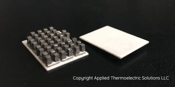
2. Apparent Simplicity – Thermoelectric cooling modules may appear straightforward at first glance. With no moving parts, complex mechanical components, lights, sounds, or vibrations, their simplicity can create a misleading impression. This often leads people to believe that anyone can easily work with thermoelectric modules and achieve the desired outcomes.

However, many individuals attempt to use these modules without success before seeking assistance. Even more concerning is when some conclude that if they cannot get the thermoelectric module to perform as intended, then no one else can either. As a result, another innovative and viable thermoelectric cooling product may never come to fruition.

3. Cost-per-watt of Cooling -If cost per watt of cooling power is the sole consideration for a particular cooling application, there are instances where methods outside of thermoelectric cooling may offer a lower cost per watt. However, cost per watt is never the only factor to consider for any given application. Even if a non-thermoelectric cooling solution has a lower cost per watt, other expenses may be significant when evaluating additional factors such as reliability, size, design flexibility, environmental impact, temperature control, scalability, efficiency, maintenance, and more.

4. Limited Thermoelectric Engineering Expertise – There is a scarcity of engineering expertise available for applying thermoelectric cooling in product design, making it challenging to find qualified assistance.

Manufacturers of thermoelectric modules often direct customers to experiment with their products. When customers do not achieve the desired results, they may become discouraged and conclude that thermoelectric technology is unsuitable for their application.

5. Numerous Variables – To develop a successful product that utilizes thermoelectric cooling, numerous variables must be taken into account. While there are instances where it is clear that thermoelectric cooling is unsuitable for a specific application, most cases require the expertise of a skilled engineer, along with experience, careful consideration, and computer simulations to make an informed determination.

How Fast do Thermoelectric Cooling Modules Get Cold?

The video below shows how fast a thermoelectric / Peltier module can get cold. It also shows how fast a thermoelectric / Peltier module gets hot.

What is a Multi-Stage or Cascade Thermoelectric Cooler Module?

A multi-stage thermoelectric cooling module is often referred to as a cascade thermoelectric module. 

These multi-stage modules are designed to achieve significantly higher temperature differences between the hot and cold sides compared to single-stage modules, resulting in much lower temperatures on the cold side. 

In a multi-stage configuration, additional single-stage modules are connected to the hot side of the first stage to enhance cooling. Each new stage added requires more cooling power than the previous one, which means it is either larger to accommodate more thermoelectric couples or maintains the same size but has a higher couple density. 

Generally, multi-stage thermoelectric coolers consume considerably more electrical power and have lower cooling rates than comparable single-stage thermoelectric modules.

a three stage cascade stacked thermoelectric module
3-stage cascade stacked thermoelectric multi-stage module
A 2-stage cascade stacked thermoelectric cooling module
2-stage cascade thermoelectric cooling module showing p and n-type semiconductors and copper interconnects between semiconductors
dual stage multi-stage cascade thermoelectric cooler module Peltier module
Multi-state cascade thermoelectric cooler module [Peltier cooler module]
dual stage multi-stage cascade thermoelectric cooler module Peltier module
Multi-state cascade thermoelectric cooler module [Peltier cooler module] rendering

Why does Thermoelectric Cooling Require both a p-type and n-type Semiconductor?

Thermoelectric cooling modules can be constructed using either all p-type or all n-type semiconductors. However, this approach results in a thermoelectric module that is not very practical. 

For instance, consider a schematic of a thermoelectric module composed solely of n-type semiconductors. In this design, the n-type semiconductors are electrically connected in parallel. 

The challenge arises when there is a need to enhance the cooling capacity to a practical level. Increasing cooling requires many n-type semiconductors, but adding more in parallel significantly reduces the electrical resistance of the module. This reduction leads to a substantial increase in the electrical current needed to operate the thermoelectric module, resulting in impractically high current levels that are often unattainable.

A thermoelectric cooling module [Peltier Cooling Module] made from only n-type thermoelements with each thermoelement wired electrically parallel. This shows the flow of electrons and heat flow directions. To move an appreciable amount of heat, more n-type thermoelements need to be added. However this lowers the electrical resistance of the module and raises the required electrical current to impractical levels.
n-type electrically parallel semiconductor thermoelectric cooling module [Peltier Cooling module] wired electrically parallel. To increase cooling capacity to be practical, more n-type elements are required. This reduces the electrical resistance of the module and increases the required electrical current to impractical levels.
Similar to the all n-type module mentioned earlier, the schematic below consists entirely of p-type semiconductors. The same practical challenges encountered with the n-type module also apply here. 
 
It is noteworthy to compare the configurations of purely n-type and purely p-type modules. By simply altering the type of semiconductor while keeping the direction of electrical flow unchanged, the direction of heat flow is completely reversed.
A thermoelectric cooling module [Peltier Cooling Module] made from only p-type thermoelements with each thermoelement wired electrically parallel. This shows the flow of electrons and heat flow directions. To move an appreciable amount of heat, more p-type thermoelements need to be added. However this lowers the electrical resistance of the module and raises the required electrical current to impractical levels.
p-type electrically parallel semiconductor thermoelectric cooling module [Peltier Cooling module] wired electrically parallel. To increase cooling capacity to be practical, more p-type elements are required. This reduces the electrical resistance of the module and increases the required electrical current to impractical levels.
If connecting all n-type or all p-type semiconductors in parallel presents issues, why not connect them in series instead? 
 
The following illustrations demonstrate why this approach is problematic. The electrical connections, typically made of copper, are also excellent conductors of heat. When the semiconductors are connected in series, heat from the hot side can conduct to the cold side, undermining the cooling effect. This phenomenon is referred to as a thermal short circuit. 
 
Therefore, connecting two n-type or two p-type semiconductors in series does not resolve the issue.
A thermoelectric cooling module [Peltier Cooling Module] made from only n-type thermoelements with each thermoelement wired in series. This shows a thermal short circuit which reduces the thermal performance of the module. Also shows the flow of electrons and heat flow directions.
n-type electrically series semiconductor thermoelectric cooling module [Peltier Cooling module] wired in electrical series showing a thermal short circuit on the electrical connector that connects the n-type elements in series.
A thermoelectric cooling module [Peltier Cooling Module] made from only p-type thermoelements with each thermoelement wired in series. This shows a thermal short circuit which reduces the thermal performance of the module. Also shows the flow of electrons and heat flow directions.
p-type electrically series semiconductor thermoelectric cooling module [Peltier Cooling module] wired in electrical series showing a thermal short circuit on the electrical connector that connects the p-type elements in series.

The solution to the challenges of low electrical resistance, high electrical current, and thermal short circuits is to connect one p-type and one n-type semiconductor couple in series. Additional couples can then be added to enhance the cooling rate.

A schematic of thermoelectric cooling couples that show the heat flow direction, electrical current flow and charge carriers in p-type and n-type semiconductors
Thermoelectric cooling semiconductors in series showing heat flow direction, current flow direction and charge carriers

What are the Applications of Thermoelectric / Peltier Cooling?

A top view of a VoltaTherm® battery thermal management system for a lithium-ion battery module and pack. The image shows a solid-state battery thermal management system (BTMS / BTM) fitted to a ParaThermic® battery module / pack.
A VoltaTherm® battery thermal management system for module and pack utilizing prismatic battery cells.

Military

  1. Thermoelectric Camouflage
  2. Military Thermoelectric cooled Avionics
  3. Thermoelectric Cooled Body Cooling Systems
  4. Thermal Imagers cooled by Thermoelectrics
  5. Thermoelectric cooled Infrared Detectors

Aerospace / Aviation

  1. Aerospace Thermoelectric Refrigeration
  2. Avionics Chassis Thermoelectric Cooling
  3. Black Box Thermoelectric Cooling
  4. Thermoelectric Battery Cooling and Heating
  5. Battery Thermal Management

Consumer products

  1. Thermoelectric Picnic Cooler
  2. Thermoelectric Microprocessor cooling
  3. Thermoelectric Heated and Cooled Water Dispenser

Telecommunications

  1. Thermoelectric Temperature Controlled Laser Diodes
  2. Pulsed Laser Cooling
  3. On Chip Cooling

Scientific

  1. Thermoelectric Cold Chambers

Conclusion

If you’re reading this, chances are you’re exploring thermoelectric cooling for your project, whether it’s for a product you’re designing or a problem you’re trying to solve. Understanding the science behind thermoelectric technology is the first step, but when it comes to applying that knowledge to real-world solutions, the path can get tricky—especially if you’re unsure how to turn your idea into a working product.

This article has covered the basics of thermoelectric cooling, from how Peltier modules work to the roles of n-type and p-type semiconductors, as well as their applications across industries like medical devices, automotive, military, and consumer electronics. But taking your concept to prototype, and ultimately to a market-ready solution, requires more than just understanding the technology—it takes experience in system design, module selection, efficiency optimization, assembly, and rigorous testing. That’s where we come in.

At Applied Thermoelectric Solutions, we specialize in providing tailored thermoelectric solutions. We can help you determine if thermoelectric cooling is the right fit for your application—whether you’re working on a simple cooling system or a more complex setup. Our team of experts offers comprehensive technical services, from designing your system to building and testing prototypes. Whether you need help selecting the best thermoelectric components, optimizing cooling performance, or scaling up for production, we’ll guide you through every step to ensure your project’s success.

With our experience in thermoelectrics and product development, we’re well-equipped to help you overcome your challenges, from selecting the right module and size for your application, ensuring efficient heat dissipation with heat sinks and fans, to reducing power consumption, increasing efficiency and cooling rate, and keeping costs manageable. We also specialize in optimizing current and voltage to achieve the best performance. We’re not just a supplier of technical services; we’re a partner in your product’s development journey.

If you have a thermoelectric project, don’t hesitate to reach out. Let’s work together to transform your idea into a functional, efficient, and reliable product that meets your specific needs.

Open bath thermoelectric cooling prototype test setup

Thermoelectric Engineering Services

Applied Thermoelectric Solutions provides thermoelectric engineering, modeling, and R&D services supporting solid-state thermoelectric cooling, thermoelectric generator (TEG) systems, and heat-to-electric energy conversion.

Our work focuses on physics-based analysis, system-level modeling, and experimental validation to establish realistic performance limits, guide design decisions, and reduce technical risk when conventional approaches fall short.

Core service areas include:

  • Thermoelectric feasibility studies and system analysis

  • Physics-based thermoelectric and electrothermal modeling

  • Prototype development and performance validation

  • Advanced thermoelectric R&D and novel system architectures

Talk directly with an engineer to evaluate whether thermoelectric cooling is a viable fit for your application.

Frequently Asked Questions About Thermoelectric Cooling

How does thermoelectric cooling work?

Thermoelectric cooling works by using an electrical current to move heat from one side of a semiconductor device to the other through the Peltier effect. When current flows, heat is absorbed on one side of the device (the cold side) and rejected on the opposite side (the hot side). The amount of cooling depends on the cold-side temperature, material properties, electrical current, ambient conditions, and how effectively heat is removed from the hot side.

A thermoelectric cooler (TEC) uses electrical power to move heat from one side of a device to the other for cooling or heating. A thermoelectric generator (TEG) operates in reverse, converting a temperature difference into electrical power. In many cases, the underlying hardware is similar, but the operating mode and system design are different.

In real systems, thermoelectric cooling performance is often limited by misaligned expectations, poor system design, and mismatch between the thermoelectric module and the application. Underestimated thermal interface resistances, ineffective heat rejection, and improper electrical operating conditions can significantly reduce performance. All of these factors must be aligned to achieve expected results.

The coefficient of performance (COP) describes the ratio of heat moved to electrical power consumed in a thermoelectric cooling system. COP depends on temperature difference, electrical current, and overall system design. These factors are interdependent, and improvements in one area can partially or fully compensate for limitations in another under specific operating conditions.

Thermoelectric cooling can produce very low or very high temperatures under the right conditions. Achieving ice formation or boiling requires careful system design, effective heat rejection, and appropriate electrical operating conditions. Whether these outcomes are achievable depends on application requirements, constraints, and system-level tradeoffs evaluated during design.

Using These Images in Your Work?

You are free to use our images on this page, as long as the required citations are provided.

However, please do not modify the images without contacting us.

Please cite any used image as follows:

Copyright Applied Thermoelectric Solutions LLC, “How Thermoelectric Cooling Works”,  www.thermoelectricsolutions.com/how-thermoelectric-cooling-works/

Did You Like This Post?

We would greatly appreciate it if you could leave a comment to let us know your thoughts on this post. 

Your feedback and suggestions are highly valued and we welcome all comments and tips. 

Thank you for taking the time to share your input with us.

6 Responses

  1. The technology is superior and developed to portable products use. is there any technology available for replacement to HVAC large air cooling systems from higher room temperatures to cooldown to thermal comfort conditions of 20 to 22*c with air quantity of 400 cubic feet per minute air per ton of refrigeration cooling. Please share the above guidance document in email.

  2. Thank you for your comment! Thermoelectric cooling technology is indeed capable of being used in larger systems, but there would need to be a reason to choose it over more traditional technologies like vapor compression refrigeration.

    For example, if you really need one of the unique advantages of thermoelectric cooling—such as its ability to operate without refrigerants or its compact nature—then a thermoelectric system could be designed specifically for that purpose. The tradeoff would depend on the ambient temperature, as well as the cost and efficiency (COP), which may not always be as favorable for larger-scale systems compared to conventional HVAC. So, the real question becomes: is the advantage that only thermoelectric cooling provides worth the tradeoff in terms of cost and performance?

    We’d be happy to help you figure out whether it makes sense for your application and guide you through the options available. Let me know if you’d like more details or a deeper dive into this topic!

  3. For colder regions electrically heated blankets are very common in use. Why , for hotter regions , TEC based cold blankets are not in fashion. ? Why so big a room is being cooled using refrigerant based AC. for sleeping in nights. ?

    1. Thank you for the comment!

      Heated blankets are an excellent way to save energy because instead of heating an entire room or house, you can heat just the bed at night, significantly reducing energy use and providing cost savings.

      Similarly, your question about why thermoelectric (TEC) cooling blankets aren’t more common is a great one. If we could apply the same cost-saving concept in hot climates or during hot seasons, a TEC blanket could be used to cool just the bed at night, eliminating the need to cool an entire room or house, thus saving both energy and costs.

      Interestingly, thermoelectric cooling blankets do exist, but they work a bit differently from heated blankets. Unlike heated blankets that have resistive heating elements integrated directly inside, TEC cooling modules are typically placed in a bedside unit. This unit cools a liquid, which is then circulated through the blanket. This approach tends to be more efficient and less complex than embedding TEC modules directly in the blanket itself. Additionally, it offers the advantage of reversibility—such systems can also function as a heater when needed. This heating function would likely be more efficient than a resistive blanket, as the thermoelectric unit operates as a heat pump. A heat pump has a coefficient of performance (COP) that can be greater than 100% efficient, because rather than converting 100% of the electricity into heat (as a resistive heater does), the thermoelectric cooling/heating module can transfer heat from the surrounding air to the blanket as well.

      Another idea to consider is cooling the mattress instead of the blanket. While thermoelectric or Peltier-cooled mattresses have been commercially available in the past, I’m not sure if they are still on the market today, but it’s an intriguing alternative for managing temperature while sleeping.

      Thanks again for your thoughtful question!

  4. Interesting read. Took apart a small thermal electric controlled consumer rated cooler, expecting to find a small compressor, but, found a thermal electric device. I’ve never heard of this cooling/heating concept and is good to know!

    1. Appreciate you sharing that firsthand experience with a thermoelectric cooling device. Always good to hear how people come across it in practice.

Leave a Reply

Your email address will not be published. Required fields are marked *