
How Is Heat Transferred in a Peltier Module?
A Peltier module, also called a thermoelectric module or thermoelectric cooler, transfers heat when direct (DC) current flows through pairs of p-type and n-type semiconductor elements. One side absorbs heat while the opposite side rejects heat, allowing the device to provide cooling, heating, or precise temperature control depending on current direction.
A Peltier module does not create “cold.” It pumps heat from one side to the other. For a broader explanation of how thermoelectric cooling systems operate at the system level, see How Thermoelectric Cooling Works.
The Short Answer
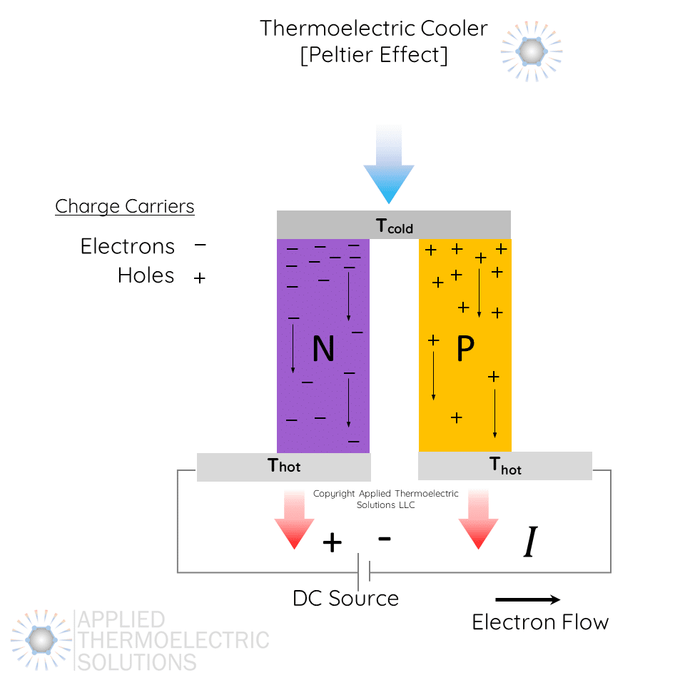
Thermoelectric / Peltier couple showing charge carriers that are holes and electrons. Also shown is hot side and cold side with electron flow direction and heat flow direction.
This heat transfer occurs through the movement of charge carriers within semiconductor materials. A junction in the context of a thermoelectric module is the interface between the semiconductor and the copper electrical interconnects that connect the semiconductors. When DC current passes through the thermoelectric couples and interconnects, heat is absorbed at the junction on one side of the semiconductor and released at the junction on the opposite side of the semiconductor.
What Is Inside a Peltier Module?

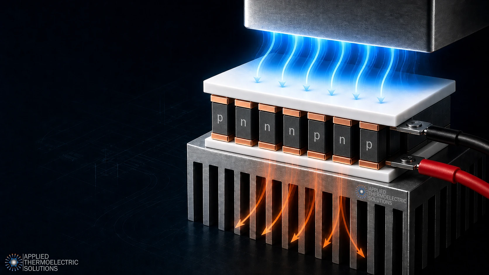
A typical Peltier module contains many thermoelectric couples placed between two ceramic plates. Each couple is made from one p-type semiconductor leg and one n-type semiconductor leg. These semiconductor legs are usually connected electrically in series and thermally in parallel.
The basic stack includes:
- a top ceramic plate
- copper interconnects
- alternating p-type and n-type semiconductor legs
- another set of copper interconnects
- a bottom ceramic plate
The ceramic plates provide mechanical structure, electrical insulation and help spread heat across the module surfaces. The copper interconnects conduct electrical current between the semiconductor legs. The p-type and n-type elements are where the thermoelectric heat-pumping effect occurs.
Why One Side Gets Cold and the Other Side Gets Hot

When current flows through the thermoelectric couples, heat is absorbed at one junction and released at the other. This is the Peltier effect.
On the cold side, the module absorbs heat from the attached surface, component, or cold plate. On the hot side, the module rejects that heat into a heat sink, liquid cold plate, or other heat-rejection structure.
If the current direction is reversed, the hot and cold sides switch. This is one reason thermoelectric modules are useful for applications that need both heating and cooling, or precise bidirectional temperature control.
Why the Hot Side Must Reject More Heat Than the Cold Side Absorbs
One of the most important practical points is that the hot side of a Peltier module must reject more heat than the cold side absorbs.
The hot side must remove:
- the heat pumped from the cold side
- the electrical input power that becomes heat inside the module (Joule heating).
This means a thermoelectric cooling system can fail even when the module itself is correctly powered. If the heat sink, fan, liquid loop, or thermal interface are improperly designed, the hot side temperature rises. As the hot side gets hotter, the temperature difference across the module increases, and the available cooling capacity decreases.
This is why Peltier module performance cannot be evaluated from the module alone. The surrounding thermal system often determines whether the module works at all.
Heat Pumping, Joule Heating, and Back Conduction

A Peltier module has several heat-transfer effects happening at the same time.
The useful effect is Peltier heat pumping. This is the heat moved from the cold side to the hot side by electrical current.
At the same time, electrical resistance inside the module creates Joule heating. Some of that heat flows toward the cold side and some flows toward the hot side.
There is also ordinary heat conduction through the module. As the hot side gets warmer than the cold side, heat naturally conducts back from the hot side toward the cold side. This back conduction works against the cooling effect.
Real performance depends on the balance between these effects:
- Peltier heat pumping
- Joule heating
- conductive heat leak
And these are all impacted by operating temperature difference and operating electrical current.
This is why simply increasing current does not always improve cooling.
At some point, additional current creates enough Joule heating that performance levels off or decreases. Operating temperature difference, whether caused by the environment or system design, can also significantly reduce performance.
What Determines Peltier Module Cooling Performance?

Peltier module cooling performance depends on the module and the system around it. In practice, improving performance often requires adjustments to both module selection and operating conditions. See Thermoelectric Module Optimization for more details.
Key factors that determine real-world performance include:
- the required cold-side temperature
- the heat load being removed
- the hot-side temperature
- the temperature difference across the module
- electrical current and voltage
- heat sink or liquid-loop capacity
- thermal interface resistance
- insulation around the cold side
- condensation and environmental conditions
- control strategy
Datasheet values are useful, but they are usually measured under specific conditions. A module that looks suitable on paper may underperform if the real heat load, mounting method, hot-side thermal resistance, or operating temperature range is different from the assumptions.
These differences are one of the main reasons thermoelectric systems are often misunderstood or incorrectly applied.
Common Misunderstandings About Peltier Heat Transfer
Several common misunderstandings lead to poor thermoelectric system performance:
A Peltier module does not eliminate heat
It moves heat from one side to the other. The hot side must still reject the heat to the surrounding environment or another thermal system.
The hot side affects the cold side
The cold side cannot be considered independently. If the hot side gets too hot, the cold side temperature will rise and cooling capacity will fall.
More current is not always better
Higher current can increase heat pumping, but it also increases resistive heating. The best operating point depends on the module, heat load, temperature difference, and system design.
Module selection is only part of the design
The heat sink, cold plate, interface materials, enclosure, insulation, power supply, and controls can determine whether the final system succeeds.
What This Means for Real Thermoelectric Cooling Design
Understanding heat transfer in a Peltier module is useful because it explains why thermoelectric cooling is a system-level design problem.
For a broader system-level explanation, see How Thermoelectric Cooling Works.
A complete thermoelectric cooling system may include:
- the thermoelectric module
- a cold plate or cooled surface
- a hot-side heat sink or liquid cold plate
- thermal interface materials
- insulation
- sensors
- power electronics
- temperature controls
- mechanical packaging
Each part affects the others. A well-designed system manages the full heat path from the cooled object, through the Peltier module, and out through the hot-side heat rejection system.
This is especially important when the application has tight temperature limits, limited space, high heat flux, condensation risk, battery or electronics constraints, or a need for stable closed-loop temperature control.
When to Use Thermoelectric Design or Simulation Support

Thermoelectric design and simulation are not just useful. They are often required to accurately predict system performance. For system-level evaluation and modeling support, see Thermoelectric Design and Simulation Services.
Thermoelectric systems involve multiple interacting variables, including heat load, temperature difference, electrical input, and thermal resistance. Many of these relationships are non-linear, and transient effects can play a major role in real-world behavior. While experienced engineers can often predict directional trends, this is rarely sufficient to ensure a design will meet its performance targets.
Without modeling, thermoelectric system design often becomes a process of trial and error. This approach can be time-consuming, expensive, and unreliable, particularly when the heat load is uncertain, space is limited, temperature requirements are tight, or the hot side is difficult to cool. It becomes even more challenging when the system must maintain precise temperature control, operate across changing conditions, or transition between heating and cooling.
Modeling and simulation allow engineers to evaluate system behavior before hardware is built. This type of analysis is essential in thermoelectric cooling system design, where multiple variables interact simultaneously. Different concepts can be compared across key metrics such as temperature, electrical current, voltage, and coefficient of performance (COP), without the time and cost associated with fabrication, instrumentation, and testing. This makes it possible to explore design tradeoffs, understand system limits, and identify viable architectures early in the development process.
Applied Thermoelectric Solutions works with engineering teams to evaluate thermoelectric cooling concepts, model system performance, and develop practical cooling architectures for real operating conditions.
If your application depends on accurate temperature control, high heat flux, or limited space, system-level modeling is often the difference between a concept that works on paper and one that works in hardware. For application-specific development, see Custom Thermoelectric Solutions or Contact Applied Thermoelectric Solutions to discuss your project.
Related Thermoelectric Design Resources
For a broader explanation of thermoelectric cooling system behavior, see:
How Thermoelectric Cooling Works
For system-level design, modeling, and optimization support, see:
Thermoelectric Design and Simulation Services
For improving module selection and operating conditions, see:
Thermoelectric Module Optimization
For application-specific development, see:
Custom Thermoelectric Solutions
Frequently Asked Questions Peltier Modules
Can a Peltier module heat and cool?
Yes. A Peltier module can heat or cool depending on the direction of current. Reversing the current reverses which side absorbs heat and which side rejects heat.
Does a Peltier module create cold?
Not exactly. A Peltier module pumps heat away from one side. That side becomes cold only if heat is removed faster than it is gained from the surrounding environment and internal heat sources.
Why does the hot side of a Peltier module get so hot?
The hot side rejects both the heat pumped from the cold side and much of the electrical input power that becomes heat inside the module. This is why hot-side heat rejection is critical.
Why does Peltier cooling become less effective at higher temperature differences?
As the temperature difference across the module increases, heat conducts back from the hot side toward the cold side. The module also has to work against a larger thermal lift, which reduces cooling capacity and efficiency.
Why is a heat sink needed on a Peltier module?
A heat sink, liquid cold plate, or other heat-rejection method is needed to remove heat from the hot side. Without effective heat rejection, the module’s hot side temperature rises and cooling performance drops.
Why is modeling important in thermoelectric cooling system design?
Thermoelectric systems involve multiple interacting variables, including heat load, temperature difference, electrical input, and thermal resistance. Many of these relationships are non-linear, and transient effects can significantly affect real-world performance. While general trends can often be predicted, accurate system behavior usually cannot be determined without modeling. Simulation allows engineers to evaluate performance, compare design options, and identify system limitations before building hardware, reducing the risk of costly trial-and-error development.
Why do thermoelectric systems often underperform compared to expectations?
Thermoelectric systems are frequently evaluated based on datasheet values that assume specific operating conditions. In real applications, performance depends on the entire thermal system, including hot-side heat rejection, thermal interfaces, heat load, and operating temperature difference. Without system-level design and modeling, these factors can reduce cooling capacity and efficiency, leading to underperformance.
Links that May Interest You
- Custom Thermoelectric Solutions
- Thermoelectric Design and Simulation Services
- Thermoelectric System Development
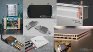
- Our Thermoelectric Cooling and Generator Work
- Thermoelectric Cooling Prototype Case Study
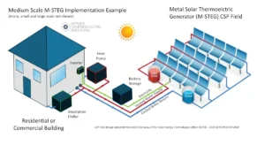
- Solar Thermoelectric Generator Case Study
- How Thermoelectric Cooling Works
- How Thermoelectric Generators Work
- ParaThermic® Battery Thermal Management Technology
- VoltaTherm® Battery Thermal Management System (BTMS)
- PowerBeam™ Wireless Power Transfer Technology
- Battery Thermal Management | After Immersion Cooling
4 Responses
Why don’t you use a transistor type Peltier module to reduce voltage at the heat dissipating end and
I ask you a question. What if a transistor could generate heat only and if we reverse engineer the same transistor to a cold dissipating transistor it would only dissipate cold and no heat will be generated.
Tim, Interesting idea. I am not familiar with the concept. Thank you for posting.
With continued use of a thermoelectric element are holes regenerated with 100% efficiency or does the performance decline with time? For heating applications how does the heat generated by a thermoelectric device compare to electrical resistive heating for the same power consumption?
Thank you, Dr. Rowlands, for your thoughtful questions. I’m happy to share some insights.
With continued use of a thermoelectric element are holes regenerated with 100% efficiency or does the performance decline with time?
In thermoelectric cooling and thermoelectric power generation, a hole is simply the absence of an electron when an electron moves from the valence band to the conduction band. The material does not have a limited supply of holes and they are not “used up” during operation. Charge carriers continually move within the semiconductor lattice, so a thermoelectric module does not lose performance because of hole depletion.
Any long-term performance change in a thermoelectric cooler or thermoelectric generator is usually caused by material diffusion, thermal cycling fatigue, or wear at solder and contact interfaces. High quality thermoelectric modules operated within their temperature limits typically show very little degradation over time. This is one reason proper design, modeling, and thermal management are important when integrating thermoelectric technology into a system.
For heating applications how does the heat generated by a thermoelectric device compare to electrical resistive heating for the same power consumption?
For heating applications, the heat output from a thermoelectric module and a resistive heater will be the same if the electrical resistance, voltage, and current are the same. Both convert electrical power into resistive (Joule) heating. The difference is that a thermoelectric module can also pump heat from its cold side to its hot side. This added pumped heat can raise the total heat output and give the system a coefficient of performance greater than one. Under the right operating conditions, this can make thermoelectric heating more effective than simple resistive heating.