Transient Thermoelectric Pulse Cooling
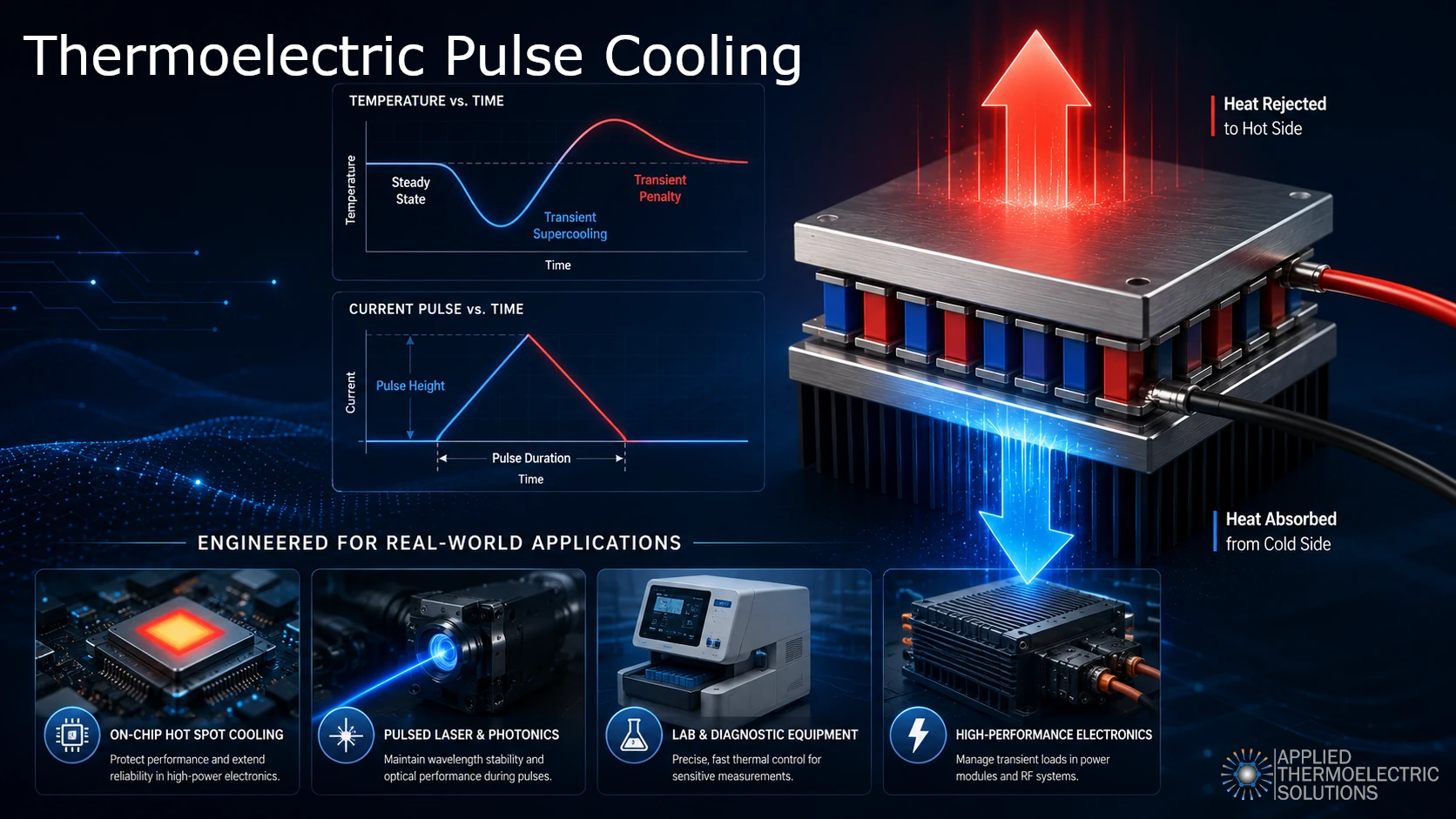
Transient thermoelectric pulse cooling is a method in which a controlled electrical current pulse is applied to a thermoelectric cooler to achieve a useful short-duration temperature drop below the steady-state operating temperature. This temporary cooling effect is often called transient supercooling.
When designing a thermoelectric pulse cooling system, the goal is to generate the right amount of additional cooling from the pulse without exceeding the limitations of the thermoelectric module or the surrounding system.
One critical constraint is hot-side solder temperature. A pulse may be electrically possible, but it is only useful if the module, interfaces, heat sink, and cooled object remain within acceptable thermal and reliability limits. This is why transient thermoelectric pulse cooling should be evaluated with a time-dependent thermal model rather than by current alone.
The pulse cooling effect occurs at the start of the current pulse. Peltier cooling begins very quickly at the thermoelectric junction, while Joule heat is generated throughout the thermoelectric elements and takes more time to diffuse through the device. This time separation can create a brief period of additional cooling before the delayed heat produces a recovery period or temperature rise known as the transient penalty.
This pulse cooling behavior matters because many real thermal problems are not steady state. Lasers, sensors, semiconductor devices, power electronics, microprocessors, and other advanced hardware can experience short-duration heat loads or localized hot spots that are much more severe than their average operating conditions. Pulse cooling can enable the needed additional cooling without using more complex or expensive thermoelectric setups such as multistage thermoelectric modules.
Transient thermoelectric pulse cooling is different from standard PWM control. The goal of PWM is to regulate average TEC current and cooling to a level at or below the current that produces maximum steady-state cooling. PWM uses a high switching frequency to achieve this. Transient pulse cooling, on the other hand, is a strategy where the current is pulsed above the steady-state current that produces maximum cooling with the goal of creating additional useful cooling, not regulating cooling below maximum cooling.
In short, one regulates current and cooling at or below maximum steady-state levels and one takes advantage of the time separation between Peltier cooling and Joule heat diffusion to produce more useful cooling for a short duration.
This article summarizes transient thermoelectric pulse cooling research and explains why time-dependent modeling is the best first step to evaluate whether pulse cooling is the right fit for a target application.
Why Transient Pulse Cooling Matters

Thermoelectric coolers are often evaluated using steady-state performance values such as current, voltage, heat pumping, COP, and maximum temperature difference. These values are useful, but they do not fully describe what happens when the thermal problem occurs over a short period of time.
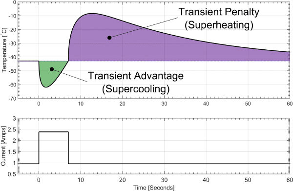
The transient pulse cooling effect occurs at the start of the current pulse. Peltier cooling begins very quickly at the thermoelectric junction, while Joule heat is generated throughout the thermoelectric elements and takes more time to diffuse toward the cold side. This time separation can create a brief period where the cold side temperature drops below the steady-state operating temperature.
That useful short-duration cooling behavior is known as the transient advantage. The transient advantage depends on how much the temperature drops, how long the additional cooling lasts, and whether the cooling occurs during the time window required by the application.
After the pulse, the delayed Joule heat can raise the cold side temperature above its normal steady-state path. That post-pulse temperature rise is known as the transient penalty.
The engineering question is not simply whether a pulse can create transient supercooling. The real question is whether the pulse cooling magnitude and duration can be designed to provide the required cooling benefit while keeping the thermoelectric module and surrounding system within their allowable operating limits.
Transient Advantage and Transient Penalty
Transient thermoelectric pulse cooling is useful only if the electrical current magnitude and duration can be engineered to provide the cooling benefit needed for the application in a practical and reliable way.
A current pulse can create:
- A lower minimum cold-side temperature
- A shorter time to reach a target temperature
- A temporary increase in cooling capacity
- A delayed temperature overshoot after the pulse
- Added electrical power consumption
- Additional heat that must be rejected by the hot side
For this reason, pulse cooling should not always be judged only by the lowest temperature reached during the pulse. It should be evaluated using a system-level metric that includes the cooling benefit, the timing of that benefit, the post-pulse recovery behavior, and the allowable temperature limits of the module and system.
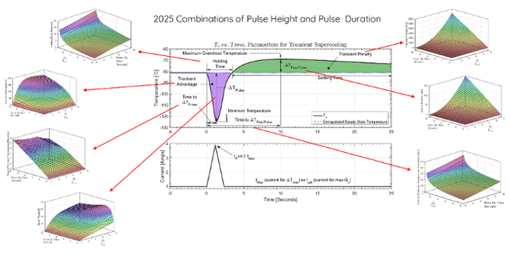
In the research summarized here, pulse height and pulse duration were varied to determine where the net transient advantage could be maximized. For many real applications, however, the main requirement is not simply maximizing net cooling. The main requirement is whether the system can be designed to provide the required amount of cooling over the required time period without exceeding practical constraints.
Pulse Cooling Is Not the Same as PWM Control

The goal of PWM is to regulate average TEC current, and therefore cooling, at or below the current that produces maximum steady-state cooling. PWM uses a high switching frequency to achieve this. At that frequency, the thermoelectric module and attached thermal mass respond mainly to the average current and cooling level, not to each individual switching event.
Transient pulse cooling, on the other hand, uses the current pulse as a deliberate thermal event. The current is pulsed above the steady-state current that produces maximum cooling with the goal of creating additional useful cooling for a short duration, not regulating cooling below maximum steady-state cooling.
The pulse magnitude and duration must be engineered to create a useful cold-side temperature drop over the required duration for the application. Pulse height, pulse duration, thermal mass, interface resistance, hot-side temperature, and heat rejection must be evaluated together because they are system-level variables that change depending on the application.
In short, PWM regulates average current and cooling at or below maximum steady-state levels, while transient pulse cooling takes advantage of the time separation between Peltier cooling and Joule heat diffusion to produce more useful cooling for a short duration.
Why Steady-State Thermoelectric Equations Are Not Enough
Steady-state thermoelectric equations are useful for estimating module behavior after temperatures and heat flows have settled. They can help estimate cooling capacity, voltage, input power, COP, and maximum temperature difference.
Transient pulse cooling requires a different approach because the temperature distribution inside the thermoelectric elements changes with time. The model must account for:
- Peltier cooling and heating at the junctions
- Volumetric Joule heat generation
- Heat conduction from the hot side to the cold side of the module
- Heat diffusion through the thermoelectric elements
- Thermal mass and thermal capacitance
- Interface resistance
- Heat spreading
- Hot-side heat exchanger heat rejection
- Time-dependent current input
- Temperature-dependent material properties
- Module temperature limits, including hot-side construction and solder limits
- System level variables
Because these variables are temperature dependent, they change during the pulse and recovery period, transient thermoelectric cooling must be modeled as a time-dependent thermal problem.
Modeling Transient Thermoelectric Pulse Cooling
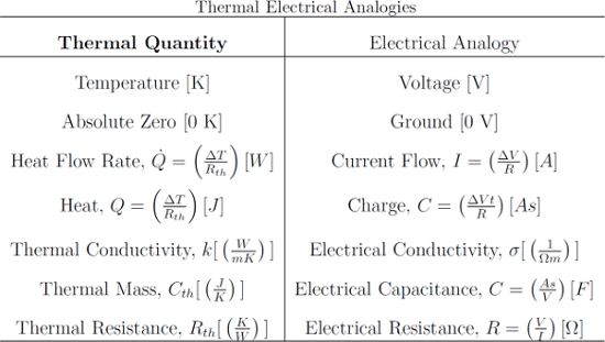
A transient thermoelectric pulse cooling model must capture both the electrical and thermal behavior of the device. One approach is to use electrical-thermal analogies and represent the thermoelectric elements as a distributed network.
In this type of model:
- Temperature is analogous to voltage
- Heat flow is analogous to electrical current
- Thermal resistance is analogous to electrical resistance
- Thermal capacitance is analogous to electrical capacitance
- Joule heating and Peltier effects are represented as time-dependent heat sources
This allows the thermoelectric element to be divided into many finite elements so the model can simulate how heat moves through the thermoelectric material over time.
For pulse cooling, this is important because the cooling effect and heating effect do not arrive at the cold side at the same time. A distributed transient model can show when the pulse creates useful supercooling, when the penalty begins, how hot-side temperature evolves, and how the design variables affect the result.
A useful model can also show whether the desired pulse strategy remains within allowable module and system limits. This matters because an aggressive pulse may increase the initial cooling benefit but also increase Joule heating, hot-side temperature rise, and the risk of exceeding internal module constraints.
Optimizing Pulse Height and Pulse Duration

The performance of transient thermoelectric pulse cooling depends strongly on pulse shape, pulse height, and pulse duration.
A pulse that is too small may not create meaningful supercooling. A pulse that is too large or too long may create excessive Joule heating, hot-side temperature rise, and a large post-pulse temperature penalty. The best pulse depends on the goals and requirements of the system it is designed for.
In practical design, the optimum pulse is not necessarily the largest pulse the power supply can deliver. The pulse must be limited by the thermoelectric module construction, solder temperature, ceramic and metallization limits, thermal interface materials, hot-side heat rejection, and the allowable temperature of the cooled object.
A useful pulse strategy maximizes the required cooling effect while keeping the module and system inside their allowable operating limits.
Important pulse and system variables include:
- Starting current
- Pulse current height
- Pulse duration
- Pulse shape
- Thermal load timing
- Heat source size
- Thermoelectric element geometry
- Module construction limits
- Hot-side solder temperature
- Interface resistance
- Heat sink or liquid block performance
- Heat spreader thermal conductivity
- Thermal mass of the cooled object
- Ambient temperature
- Starting and ending temperature requirements
This is one reason transient pulse cooling is difficult to optimize by intuition. Increasing pulse current can increase the initial Peltier cooling effect, but it also increases Joule heating, hot-side temperature rise, and post-pulse thermal penalty. The best pulse height and duration depend on the complete system.
Applications of Transient Thermoelectric Pulse Cooling

Applications of Transient Thermoelectric Pulse Cooling
Transient thermoelectric pulse cooling is most relevant when a system needs short-duration cooling, fast thermal response, or control of localized thermal events. It is not a replacement for every steady-state thermoelectric cooler. It is a tool for applications where the timing, location, and duration of the heat load matter.
Some applications are direct fits for transient pulse cooling. Others are related transient thermoelectric control problems where the same modeling principles are important, including thermal mass, interface resistance, heat spreading, current control, hot-side temperature limits, and time-dependent temperature response.
Pulsed Laser Sensors and Laser Diode Systems
Pulsed lasers, laser sensors, and laser diode systems can experience short thermal events that affect wavelength stability, output power, measurement accuracy, or device reliability. Transient thermoelectric pulse cooling may help provide additional cooling during the critical operating window without sizing the entire system around a worst-case steady-state condition.
In these systems, the value of pulse cooling is tied to timing. The cooling benefit must occur during the laser pulse, measurement window, or temperature-sensitive operating period.
On-Chip Hot Spot Cooling
Microprocessors, GPUs, ASICs, and other high-power semiconductor devices can develop localized hot spots that are significantly warmer than the surrounding chip. These hot spots may occur during short periods of peak activity, even when the average device temperature appears acceptable.
Embedded or localized thermoelectric coolers have been studied as a way to apply cooling directly where and when the hot spot occurs. For these systems, transient modeling is especially important because the heat source is localized, the thermal mass is small, and the useful cooling window may be short.
3D Stacked Chips and Advanced Semiconductor Packaging
As electronics move toward chiplets, 3D stacking, and heterogeneous integration, heat can become trapped inside the package. Internal hot spots may be difficult to reach with conventional external cooling alone.
Transient thermoelectric cooling can be relevant when localized cooling must be synchronized with short-duration heat generation inside the package. In these applications, the thermal path, interface resistance, package geometry, and heat spreader design can strongly affect whether pulse cooling produces a useful benefit.
Dynamic Power Electronics, RF Devices, and Pulsed Electronics
Power electronics, RF devices, microwave systems, and high-current electronics often experience transient power spikes rather than constant heat generation. A cooling system may be acceptable for the average load but still allow excessive peak temperatures during short operating events.
Transient thermoelectric modeling can help determine whether a pulse-current strategy could reduce peak temperature, improve short-duration thermal response, or delay temperature rise during high-power operating periods.
Photonics, Optoelectronics, and Optical Communications
Photonics, laser diodes, LEDs, optical transceivers, and other optoelectronic devices are sensitive to temperature. Even small temperature changes can affect wavelength, output power, signal quality, efficiency, noise, and stability.
Transient thermoelectric cooling may be useful where temperature control is needed during a specific pulse, measurement, communication cycle, or short operating interval. In these applications, the goal may be wavelength stability, improved signal performance, or protection from brief thermal excursions.
Infrared Detectors, CCDs, CMOS Sensors, and Precision Imaging
Image sensors and infrared detectors often require temperature control to reduce thermal noise, dark current, and signal drift. Many of these applications use thermoelectric cooling for compact, sub-ambient temperature control.
While not every imaging application uses pulse supercooling, transient thermoelectric modeling is important for evaluating cooldown time, temperature stability, thermal mass, and system response during changing operating conditions. This is especially important for compact imaging systems where size, power, and thermal response must be balanced.
Medical Diagnostics and Rapid Thermal Cycling
PCR systems, molecular diagnostic instruments, and laboratory devices often use thermoelectric modules because they can heat and cool precisely in a compact package. These systems may require fast transitions between temperature setpoints, tight temperature control, and predictable thermal response.
These applications are not always the same as transient pulse supercooling, but they share many of the same engineering challenges: transient response, thermal mass, interface resistance, overshoot control, current control, and accurate temperature prediction.
Semiconductor Test and Characterization
Semiconductor test and characterization can involve short thermal events, controlled sub-ambient conditions, and rapid changes in device operating state. Transient thermoelectric modeling can help evaluate whether pulse cooling, fast temperature control, or localized cooling could improve test repeatability or better simulate real operating conditions.
For these applications, the thermoelectric module is only one part of the problem. The fixture, interface materials, device package, sensor placement, and control method all influence the measured response.
Electro-Optical and Defense Sensing Systems
Electro-optical systems, infrared sensing hardware, aerospace electronics, and defense-related sensors often combine compact packaging with temperature-sensitive performance. These systems may need fast thermal response, short-duration cooling, or stable operation during changing electrical loads and environmental conditions.
Transient thermoelectric cooling may be relevant where the system needs a brief cooling advantage during a measurement window, pulse event, or high-sensitivity operating mode.
Other Related Transient Cooling Applications
Other related areas include compact instrumentation, scientific measurement systems, localized electronics cooling, and specialized thermal control systems where short-duration heat loads matter. In these cases, the key value is often not pulse cooling alone, but the ability to model transient thermoelectric behavior accurately at the system level.
The practical question is whether a controlled current pulse can provide the required temperature response without exceeding module limits, hot-side solder temperature constraints, interface limits, power limits, or system reliability requirements. That question is best answered through transient thermoelectric modeling before hardware testing begins.
Practical Engineering Implications
Transient thermoelectric pulse cooling should be evaluated at the system level. The module alone does not determine whether pulse cooling will work.
A useful model should include the thermoelectric module, heat source, interface materials, heat spreader, cooled object, hot-side heat rejection path, control approach, and timing of the thermal load.
For real product development, the most important questions are:
- What thermal event must be controlled?
- How long does the event last?
- How much temperature reduction is required?
- Where is the heat generated?
- How quickly must the system respond?
- How much post-pulse heating is acceptable?
- Can the hot side reject the additional heat?
- What are the hot-side temperature and solder-temperature constraints?
- Do the thermal interfaces, heat sink, and cooled object remain within their limits?
- Does the pulse strategy improve the system compared with a larger steady-state cooler?
These questions determine whether pulse cooling is a useful design path or only an interesting transient effect.
Pulse cooling is not about pushing a thermoelectric module blindly beyond its limits. It is about using transient modeling to find the highest useful cooling performance the module and system can safely support.
Why Modeling Should Come Before Hardware Testing

It may be tempting to test a thermoelectric module directly to determine whether pulse cooling is a good fit. However, module-level testing alone often does not answer the most important engineering question.
The goal of transient pulse cooling is not simply to apply more current. The goal is to maximize short-duration cooling while staying inside the real limits of the thermoelectric module and the system around it. Those limits may include hot-side solder temperature, ceramic temperature, metallization and interconnect limits, thermal interface materials, heat sink performance, power supply limits, and the allowable temperature of the cooled object.
This makes trial-and-error testing difficult. A test program that simply increases current pulse height or pulse duration can destroy modules before the useful operating window is understood. Even when a module survives, the result may not apply to the final product because pulse cooling depends heavily on the complete system.
Pulse cooling performance is affected by the heat source, cooled object, thermal mass, interface resistance, heat spreader, heat sink, fan or liquid cooling system, ambient temperature, starting temperature, current pulse shape, and control strategy. These variables interact in a time-dependent and nonlinear way.
Because of that nonlinearity, it is difficult to estimate the optimum pulse height and duration by engineering judgment alone. A pulse that appears reasonable may produce too much delayed Joule heating. A pulse that appears aggressive may be acceptable if the hot-side temperature and solder limits remain controlled. A model can evaluate these tradeoffs before hardware is damaged.
A model-based approach can help with:
Time savings: Simulation can compare many pulse heights, durations, module geometries, heat sink conditions, interface materials, and heat load profiles faster than building and testing each option.
Module protection: Modeling can identify operating regions that exceed solder temperature, hot-side limits, or other module constraints before destructive testing occurs.
Nonlinear behavior: Transient pulse cooling is not intuitive. Peltier cooling, Joule heating, heat diffusion, thermal mass, and interface resistance interact over time. Modeling can reveal behavior that would be difficult to predict from simple estimates.
Deliberate optimization: Modeling allows the pulse and system design to be optimized toward a required cooling magnitude and time duration while respecting module and system constraints.
Better testing: Testing is still important, but it is more effective when used to verify a model-guided design rather than to search blindly for an operating point.
For transient thermoelectric pulse cooling, modeling helps define the safe and useful design space before prototypes are built, tested, and potentially damaged.
Thermoelectric Pulse Cooling Modeling and Engineering Support

Applied Thermoelectric Solutions helps evaluate thermoelectric systems from a model-based, system-level perspective. For transient cooling applications, this can include analysis of thermoelectric modules, pulse-current strategies, heat source timing, interface resistance, heat spreading, thermal mass, and hot-side heat rejection.
Transient pulse cooling is not simply a matter of applying more current. The electrical input, thermoelectric element behavior, thermal interfaces, and system response must be evaluated together.
For pulse cooling applications, Applied Thermoelectric Solutions can evaluate whether a proposed current pulse improves cooling performance without exceeding module or system limits. This includes modeling the cold-side response, delayed Joule heating, hot-side temperature rise, solder temperature constraints, heat rejection path, and post-pulse recovery behavior.
The objective is to find a practical operating region where the required cooling event is achieved without damaging the thermoelectric module or compromising system reliability.
If your application involves short-duration heat loads, localized hot spots, laser or sensor temperature control, rapid thermal cycling, or advanced thermoelectric cooling design, Applied Thermoelectric Solutions can help determine whether transient thermoelectric pulse cooling is commercially useful and practical for your system.
Original Research Behind This Guide
This page is based in part on published research by the Founder and CTO of Applied Thermoelectric Solutions on transient thermoelectric supercooling, pulse-current modeling, response surface optimization, and thermoelectric cooling of heat-generating objects.
Published Paper: Response Surface Perspective
Peltier Supercooling with Isosceles Current Pulses: A Response Surface Perspective
This paper investigated pulse height and pulse duration using SPICE-based electrical-thermal analogies to identify operating regions where net transient cooling could be improved. The study used pulse durations from 0.1 to 10 seconds and pulse heights from 1.01 to 6.0 times the steady current.
Published Paper: Cooling a Heat-Generating Object
Peltier Supercooling with Isosceles Current Pulses: Cooling an Object with Internal Heat Generation
This paper studied a more realistic system with a thermoelectric module attached to a heat-generating object. It examined cooling rate, power consumption, and COP during pulse operation. A key conclusion was that cooling rate can increase during pulsing, but COP is reduced in most current-pulse cases.
Full Thesis Archive
Transient Thermoelectric Supercooling: Isosceles Current Pulses from a Response Surface Perspective and the Performance Effects of Pulse Cooling a Heat Generating Mass
This thesis provides the deeper modeling foundation behind the later published work, including thermocouple modeling, system modeling, interface resistance, heat spreader effects, internal heat generation, temperature distribution, and continuous pulsing.
Buttons: View Thesis Archive / Download Thesis PDF
Transient pulse cooling is not simply a matter of applying more current. The electrical input, thermoelectric element behavior, thermal interfaces, and system response must be evaluated together.
For pulse cooling applications, Applied Thermoelectric Solutions can evaluate whether a proposed current pulse improves cooling performance without exceeding module or system limits. This includes modeling the cold-side response, delayed Joule heating, hot-side temperature rise, solder temperature constraints, heat rejection path, and post-pulse recovery behavior.
The objective is to find a practical operating region where the required cooling event is achieved without damaging the thermoelectric module or compromising system reliability.
If your application involves short-duration heat loads, localized hot spots, laser or sensor temperature control, rapid thermal cycling, or advanced thermoelectric cooling design, Applied Thermoelectric Solutions can help determine whether transient thermoelectric pulse cooling is commercially useful and practical for your system.
Frequently Asked Questions
What is transient thermoelectric pulse cooling?
Transient thermoelectric pulse cooling is a method of applying a controlled current pulse to a thermoelectric cooler to create a short-duration temperature drop below the comparable steady-state operating condition. This temporary cooling effect is often called transient supercooling.
How is pulse cooling different from PWM control?
PWM control regulates average TEC current and cooling at or below the current that produces maximum steady-state cooling. It uses a high switching frequency so the thermoelectric module and attached thermal mass respond mainly to the average current and cooling level.
Transient pulse cooling is different. The current is pulsed above the steady-state current that produces maximum cooling to create additional useful cooling for a short duration. It takes advantage of the time separation between fast Peltier cooling and delayed Joule heat diffusion.
Why can a thermoelectric cooler briefly cool below its steady-state temperature?
Peltier cooling occurs quickly at the thermoelectric junction, while Joule heat is generated throughout the thermoelectric elements and takes time to diffuse to the cold side. This time separation can briefly lower the cold side temperature below the comparable steady-state value.
What is transient advantage?
Transient advantage is the useful short-duration cooling benefit created by a current pulse. It depends on the magnitude of the temperature drop, how long the drop lasts, and whether the cooling occurs during the time window required by the application.
What is transient penalty?
Transient penalty is the temperature rise that can occur after the pulse as delayed Joule heat reaches the cold side. A useful pulse cooling strategy must consider both the cooling benefit and the post-pulse heating penalty.
What applications can use transient thermoelectric pulse cooling?
Transient thermoelectric pulse cooling may be useful for applications that need short-duration cooling, fast thermal response, or localized temperature control. Examples include pulsed laser sensors, laser diode systems, on-chip hot spot cooling, 3D stacked chips, dynamic power electronics, RF devices, photonics, infrared detectors, precision imaging systems, medical diagnostics, rapid thermal cycling, semiconductor test, and electro-optical sensing systems.
Some of these are direct pulse cooling applications. Others are related transient thermoelectric control problems where the same modeling principles are important.
Is thermoelectric pulse cooling the same as overdriving a Peltier module?
No. Transient thermoelectric pulse cooling is not about blindly overdriving a module. The goal is to generate useful short-duration cooling without exceeding the limitations of the module or system.
One important constraint is hot-side solder temperature. A pulse may be electrically possible, but it is only useful if the module, interfaces, heat sink, cooled object, and surrounding system remain within acceptable thermal and reliability limits.
Can transient pulse cooling improve COP?
It depends on the system, pulse shape, heat load, and performance metric being used. Pulse operation can improve short-duration cooling behavior in some cases, but it can also increase power consumption and post-pulse heating. A transient model is needed to evaluate the tradeoff.
Why is modeling important for thermoelectric pulse cooling?
Pulse cooling depends on time-dependent and system-level behavior. A useful model must account for Peltier cooling, Joule heating, heat diffusion, thermal mass, interface resistance, hot-side heat rejection, solder temperature limits, and the timing of the thermal load.
Modeling helps determine whether a current pulse can provide the required cooling benefit without exceeding module or system limits.
Why not just test pulse cooling on a thermoelectric module?
Testing alone can be slow, expensive, and destructive. Because pulse cooling is nonlinear, it is difficult to estimate the optimum pulse magnitude and duration by trial and error. Testing operating points blindly can destroy modules before the useful design window is understood.
Modeling helps identify the safe and useful operating region first, so hardware testing can be used for verification rather than discovery.
Does transient thermoelectric pulse cooling work with commercial Peltier modules?
It can, but the benefit depends on the module, pulse magnitude, pulse duration, heat load, thermal interfaces, heat sink, hot-side temperature, solder temperature limits, and system design. A commercial module should be evaluated as part of the complete thermal system rather than in isolation.
Can Applied Thermoelectric Solutions help evaluate pulse cooling for a product?
Yes. Applied Thermoelectric Solutions can model transient thermoelectric cooling behavior, evaluate pulse-current strategies, analyze system-level thermal performance, and determine whether pulse cooling is practical for a specific application.
This includes evaluating cold-side response, delayed Joule heating, hot-side temperature rise, solder temperature constraints, heat rejection, interface resistance, and post-pulse recovery behavior.
Research and Technical Resources
The references below include original Applied Thermoelectric Solutions research, transient thermoelectric pulse cooling studies, hotspot cooling research, and related transient thermoelectric modeling resources.
Featured Research Most Directly Related to Transient Thermoelectric Pulse Cooling
- Piggott, Transient Thermoelectric Supercooling: Isosceles Current Pulses from a Response Surface Perspective and the Performance Effects of Pulse Cooling a Heat Generating Mass, Master’s thesis, Michigan Technological University, 2015.
- Snyder, J.-P. Fleurial, T. Caillat, R. Yang, and G. Chen, Supercooling of Peltier cooler using a current pulse, Journal of Applied Physics, 92, 1564 (2002).
- Yang, G. Chen, G. J. Ravi Kumar, A. Snyder, and J.-P. Fleurial, Transient cooling of thermoelectric coolers and its applications for microdevices, Energy Conversion and Management, (2005).
- Mao, H. Chen, H. Jia, and X. Qian, The transient behavior of Peltier junctions pulsed with supercooling, Journal of Applied Physics, 112, 014514 (2012).
- Lv, X.-D. Wang, T.-H. Wang, and J.-H. Meng, Optimal pulse current shape for transient supercooling of thermoelectric cooler, Energy, 83, 788 (2015).
- Ma, J. Yu, and J. Chen, An investigation on thermoelectric coolers operated with continuous current pulses, Energy Conversion and Management, 98, 275 (2015).
- Manno, W. Peng, and A. Bar-Cohen, Pulsed thermoelectric cooling for improved suppression of a germanium hotspot, IEEE Transactions on Components, Packaging and Manufacturing Technology, 4, 602 (2014).
- Redmond, K. Manickaraj, O. Sullivan, S. Mukhopadhyay, and S. Kumar, Hotspot cooling in stacked chips using thermoelectric coolers, IEEE Transactions on Components, Packaging and Manufacturing Technology, 3, 759 (2013).
Additional Transient Thermoelectric and Application Resources
- Hot spot cooling using embedded thermoelectric coolers, 22nd IEEE SEMI-THERM Symposium, 2006.
- Mitrani, J. Salazar, A. Turi, M. J. Garcia, and J. A. Chavez, Transient distributed parameter electrical analogous model of TE devices, Microelectronics Journal, 40, 1406 (2009).
- Manno, On-chip thermoelectric hotspot cooling, Ph.D. thesis, University of Maryland, 2015.
- Sullivan, Embedded Thermoelectric Devices for On-chip Cooling and Power Generation, Ph.D. thesis, Georgia Institute of Technology, 2012.
- Thonhauser, G. D. Mahan, L. Zikatanov, and J. Roe, Improved supercooling in transient thermoelectrics, Applied Physics Letters, 85, 3247 (2004).
- Sullivan, M. P. Gupta, S. Mukhopadhyay, and S. Kumar, Thermoelectric coolers for thermal gradient management on chip, in: ASME 2010 International Mechanical Engineering Congress and Exposition, American Society of Mechanical Engineers, 187 (2010).
- Hoyos, K. Rao, and D. Jerger, Fast transient response of novel Peltier junctions, Energy Conversion, 17, 45 (1977).
- Geometric Effects on the Transient Cooling of Thermoelectric Coolers, volume 691, Boston, Massachusetts, U.S.A., 2001.
- Lv, X.-D. Wang, C.-H. Wang, and Tian-Huand Cheng, Improvement of transient supercooling of thermoelectric coolers through variable semiconductor cross-section, Applied Energy, (2016).
- Lv, X.-D. Wang, J.-H. Meng, T.-H. Wang, and W.-M. Yan, Enhancement of maximum temperature drop across thermoelectric cooler through two-stage design and transient supercooling effect, Applied Energy, (2016).
- Q. Nguyen and K. V. Pochiraju, Behavior of thermoelectric generators exposed to transient heat sources, Applied Thermal Engineering, 51, 1 (2013).
Links that May Interest You
- Custom Thermoelectric Solutions
- Thermoelectric Design and Simulation Services
- Thermoelectric System Development
- Our Thermoelectric Cooling and Generator Work
- Thermoelectric Cooling Prototype Case Study
- Solar Thermoelectric Generator Case Study
- How Thermoelectric Cooling Works
- How Thermoelectric Generators Work
- ParaThermic® Battery Thermal Management Technology
- VoltaTherm® Battery Thermal Management System (BTMS)
- PowerBeam™ Wireless Power Transfer Technology
- Battery Thermal Management | After Immersion Cooling