Thermoelectric Battery Cooling With Heat Spreaders: Patent Background

This page discusses battery thermal management, more specifically it reviews a patent involving thermoelectric battery cooling and heating with heat spreaders positioned to improve the thermal path between battery hotspots and thermoelectric devices.
The patent was developed by Alfred Piggott, Founder and CTO at Applied Thermoelectric Solutions and other inventors while he was working at Gentherm. It is included here as technical background showing Alfred Piggott’s earlier work in thermoelectric battery cooling, battery hotspot management, heat-spreader integration, thermoelectric device placement, and system-level battery thermal design.
The central idea was straightforward but important: the performance of a thermoelectric battery cooling system depends not only on the thermoelectric device, but also on the thermal resistance between the heat-generating region of the battery and the device’s cold side.
The patented approach used a heat spreader to create a more direct, lower-resistance path between a battery hotspot and a thermoelectric device. This allowed a larger portion of the generated heat to flow toward the active cooling system and reduced the temperature rise required to drive that heat flow.
Currently, Applied Thermoelectric Solutions has developed ParaThermic® and VoltaTherm® technologies to address the these thermal-path limitations directly.
ParaThermic® batteries dramatically reduce the internal thermal resistance between the heat-generating regions of the cell and the thermal-management interface, making internal hotspots more difficult to form.
VoltaTherm® places thermoelectric modules directly at the cell-cooling system interface, eliminating the need for an intermediate heat spreader and minimizing avoidable external thermal resistance.
Thermoelectric Battery Cooling and Heating Patent Overview
A battery does not necessarily generate or store heat uniformly throughout the cell. Some regions may become hotter than others because of cell construction, current distribution, electrical resistance, state of charge, charge or discharge rate, aging, and surrounding thermal boundary conditions.
The patented concept addressed this problem by connecting a heat spreader to a hotspot or temperature-sensitive region of the battery. A thermoelectric device could then remove heat from that region during cooling or deliver heat to it during warm-up.
A thermoelectric device, also commonly called a Peltier device, can pump heat in either direction. Reversing the direction of electrical current reverses the direction of heat pumping, allowing the same solid-state device to provide both cooling and heating.
The system-level design can include:
- A battery cell or battery module
- A localized hotspot or temperature-sensitive region
- A thermally conductive heat spreader
- A thermoelectric cooling and heating device
- Thermal interfaces between the components
- Temperature sensors and controls
- Power electronics
- A waste-side heat-rejection system
The patent therefore addressed more than thermoelectric module selection. It considered the complete heat-transfer path from heat generation within the battery to heat rejection outside the system.
How Thermoelectric Battery Cooling Works

In cooling mode, the thermoelectric device absorbs heat on its cold side and pumps it to its hot side. That heat, together with the electrical power consumed by the thermoelectric device, must then be rejected through a heat sink, airflow system, liquid loop, radiator, or another heat-removal system.
The overall cooling path is:
Battery heat generation → internal battery thermal path → battery surface or hotspot interface → heat spreader → thermoelectric cold side → thermoelectric hot side → waste-side heat-rejection system
In heating mode, the current direction can be reversed so heat is pumped toward the battery. The electrical power dissipated within the thermoelectric device also contributes to heating, allowing a heating coefficient of performance greater than one under suitable operating conditions.
The performance of the complete system depends on:
- Battery internal thermal resistance
- Heat-spreader resistance
- Thermal interface resistance
- Thermoelectric module operating point
- Temperature difference across the thermoelectric module
- Available electrical power
- Controls
- Waste-side heat rejection
This is why thermoelectric battery cooling cannot be optimized by selecting a Peltier device from a catalog and attaching it to a battery. The battery, thermal path, thermoelectric device, controls, packaging, and heat-rejection system must be designed together.
Why Battery Hotspot Location Matters
Heat generated inside a battery flows through all available thermal paths according to the temperature gradients and thermal resistances associated with those paths.
In a conventional battery, some of those paths may have relatively high thermal resistance. A significant temperature difference may therefore be required to move heat from a localized hotspot toward the battery surface and cooling system.
The patented approach added a more direct, lower-resistance path from the hotspot region to the thermoelectric cooling interface.
This changed the effective thermal-resistance network.
With the added path:
- A greater portion of the generated heat could flow toward the thermoelectric device.
- Less heat had to leave through the battery’s higher-resistance paths.
- A smaller temperature gradient was required to move a given amount of heat through the new path.
- The hotspot temperature could decrease because heat was removed more effectively.
- The active cooling system could respond more directly to the region accumulating the most heat.
Heat did not flow exclusively through the new path. It continued to flow through every available path. However, the lower-resistance path carried a greater share of the total heat flow and reduced the effective thermal resistance between the hotspot and the cooling system.
The location of the hottest region can also change with operating conditions. Charge rate, discharge rate, state of charge, aging, current distribution, cell construction, and surrounding thermal conditions can all influence the internal temperature distribution.
Thermoelectric battery cooling should therefore be designed around the expected heat-generation patterns and thermal-resistance network, not only around the most convenient packaging location.
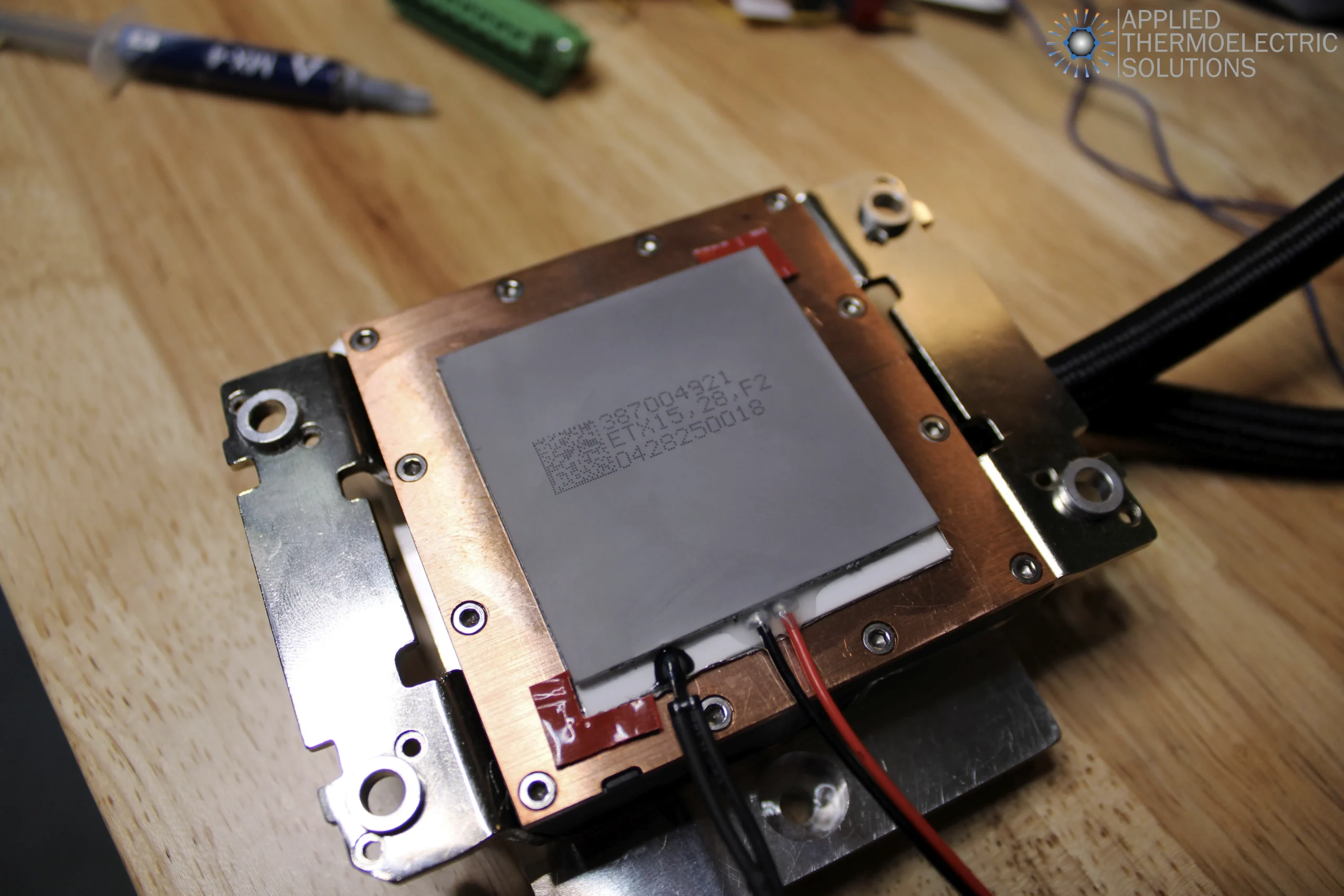
Using Heat Spreaders to Create a Lower-Resistance Thermal Path
A heat spreader is a thermally conductive component used to connect a heat-generating or temperature-sensitive region to a thermal-management interface.
In this earlier patented approach, the heat spreader connected the battery hotspot region to the thermoelectric device. Its purpose was not simply to make the battery surface temperature more uniform. It was also intended to reduce the effective thermal resistance between the hotspot and the active cooling system.
By adding a relatively direct conductive path, the heat spreader could:
- Increase heat flow from the hotspot toward the thermoelectric device
- Reduce the temperature difference needed to drive that heat flow
- Reduce the portion of heat leaving through higher-resistance paths
- Lower localized hotspot temperature
- Improve the response of the heating and cooling system
- Allow a thermoelectric device to influence a targeted battery region
The benefit depends on the heat spreader’s:
- Thermal conductivity
- Geometry
- Thickness
- Contact area
- Location
- Bonding method
- Interface resistance
- Electrical-isolation requirements
- Connection to the thermoelectric device
The heat spreader improved the available thermal path in the earlier architecture. However, it was still an intermediate heat-transfer component between the battery and the thermoelectric module.
Why Thermal-Path Resistance Affects Thermoelectric Performance
The thermal resistance between the battery and thermoelectric device affects more than the battery hotspot temperature. It also affects the operating temperature of the thermoelectric module’s cold side.
For a given heat flow, the temperature drop across a thermal path increases with thermal resistance.
If a battery is connected to the cold side of a thermoelectric device through a high-resistance path, the cold side must operate at a lower temperature to maintain the battery core or hotspot at its target temperature.
For example, if a battery hotspot must be maintained at a specified temperature, an excessive temperature drop between the hotspot and the thermoelectric device forces the module’s cold side to operate substantially colder than the battery.
This increases the temperature difference across the thermoelectric module between its hot and cold sides.
A larger thermoelectric temperature difference generally:
- Reduces available cooling capacity
- Increases the electrical input required for a given cooling load
- Lowers thermoelectric coefficient of performance (COP)
- Increases the total heat that must be rejected from the hot side
- Makes the system more sensitive to ambient temperature
- Makes heat-sink or coolant performance more critical
The earlier patented heat-spreader approach improved this condition by creating a lower-resistance path between the battery hotspot and the thermoelectric device.
Because less temperature difference was lost between the hotspot and the thermoelectric cold side, the module did not need to operate as far below the battery temperature.
This reduced the temperature lift required from the thermoelectric device and improved cooling performance compared with a less direct, higher-resistance thermal connection.
However, the heat spreader still added material resistance, interface resistance, and additional thermal path length.
VoltaTherm® improves the external thermal path further by positioning the thermoelectric module directly at the intended cell-cooling interface without an intermediate heat spreader.
Thermoelectric Device Placement for Localized Battery Cooling
Thermoelectric device placement is a system-level design decision.
Placing a thermoelectric module near the heat-generating region can reduce the thermal resistance between the battery and the cold side of the module. However, the module must also fit within the available packaging space and connect to an effective waste-side heat-rejection system.
An effective design must consider:
- Battery heat-generation patterns
- Internal cell thermal resistance
- Thermoelectric module location
- Available cell contact area
- Thermal interface resistance
- Module geometry
- Electrical connections
- Mechanical loading
- Thermal expansion
- Sensor placement
- Condensation risk
- Waste-side cooling
- Assembly and serviceability
A heat spreader can improve performance when the thermoelectric module cannot be located directly at the preferred cooling interface.
However, if the thermoelectric device can be placed directly at the ideal cell-cooling location, adding a separate heat spreader creates additional series resistance and additional interfaces.
The best external thermal path is therefore generally the most direct practical connection between the cell and the thermoelectric module.
Pouch Cell and Battery Module Cooling Applications
The hotspot and thermal-path principles can apply to pouch cells, prismatic cells, cylindrical cells, battery modules, and other battery configurations.
Pouch cells have a relatively large external surface area, but their layered internal construction can produce strong directional differences in thermal conductivity. A heat spreader can help connect a localized region of the pouch cell to a smaller thermoelectric interface when direct module placement is not practical.
At the battery module level, multiple heat spreaders or thermoelectric devices can create localized thermal zones. Different portions of the module can then receive different amounts of heating or cooling.
Potential advantages of thermoelectric battery cooling include:
- Solid-state operation
- Reversible heating and cooling
- Compact localized temperature control
- No compressor
- No refrigerant within the thermoelectric system
- Zonal control
- Integration into unusual or space-constrained systems
Whether thermoelectric cooling is appropriate depends on heat load, ambient temperature, battery temperature requirements, available electrical power, required COP, weight, cost, packaging constraints, and the effectiveness of the complete thermal path.
Technical Limitations of the Earlier Heat-Spreader Approach
The patented approach improved the thermal path between a battery hotspot and the thermoelectric cooling system. However, it did not eliminate the internal thermal resistance of the battery itself.
Heat generated inside the battery still had to reach the region connected to the heat spreader. The heat then had to pass through:
- The battery-to-spreader interface
- The heat spreader
- The spreader-to-thermoelectric interface
- The thermoelectric device
- The waste-side thermal interface and heat-rejection system
Although the heat spreader could reduce resistance compared with the alternative paths available in that design, it was not the lowest-resistance architecture theoretically possible.
Potential limitations included:
- Internal battery resistance before heat reached the spreader
- Heat-spreader material resistance
- Battery-to-spreader contact resistance
- Spreader-to-thermoelectric contact resistance
- Added material and mass
- Additional packaging volume
- Added component and assembly cost
- Electrical-isolation requirements
- Fixed hardware location relative to changing hotspot patterns
- Increased thermoelectric temperature difference
- Thermoelectric power consumption
- Waste-side heat-rejection requirements
Applied Thermoelectric Solutions later advanced the state of the art by reducing the battery’s internal thermal resistance and placing the thermoelectric device directly at the intended cell-cooling interface. These improvements are embodied in ParaThermic® and VoltaTherm® technologies.
Relationship to ParaThermic® Battery Architecture

The earlier patent created a lower-resistance external path between a battery hotspot and a thermoelectric device.
ParaThermic® batteries address the problem further upstream by reducing the internal thermal resistance of the battery itself.
ParaThermic® high-heat-transfer battery architecture is designed to improve heat flow from the heat-generating regions inside the cell to the external battery thermal-management system interface.
This produces two important effects.
First, heat can leave the battery interior with a smaller internal temperature gradient. This makes localized internal hotspots more difficult to form.
Second, more of the internally generated heat can reach the intended thermal-management interface rather than remaining concentrated within higher-resistance regions of the cell.
ParaThermic® batteries are designed to enable greater heat removal while minimizing the cooling-induced internal temperature gradients that can limit battery performance, life, charging rate, and safety.
ParaThermic® batteries do not depend on thermoelectric cooling. It can work with:
- Air cooling
- Liquid cooling
- Refrigerant cooling
- Immersion cooling
- Phase-change materials
- Two-phase cooling
- Jet impingement
- Thermoelectric cooling
- Other battery thermal management methods
Its role is to open the battery-side thermal path so the external thermal management system can interact more effectively with the heat-generating regions inside the cell.
Relationship to VoltaTherm® Solid-State Battery Thermal Management

VoltaTherm® addresses the external thermal-management-system side of the problem.
The earlier patent used a heat spreader as an intermediate component to connect the battery hotspot to the thermoelectric device.
VoltaTherm® instead places the thermoelectric modules directly at the intended cell-cooling interface. The battery cell is heated or cooled without an intermediate heat spreader.
Eliminating the heat spreader removes:
- Heat-spreader material resistance
- Battery-to-spreader interface resistance
- Spreader-to-thermoelectric interface resistance
- Added thermal path length
- Added component cost
- Added assembly complexity
- Added packaging volume
- Added mass
A heat spreader can improve an indirect or poorly located thermal path. However, when the thermoelectric device is positioned directly at the preferred cell-cooling interface, an additional spreader would add unnecessary thermal resistance.
The direct VoltaTherm® thermal connection allows the thermoelectric cold side to operate closer to the required battery temperature.
For a given battery heat load and target cell temperature, reducing the external thermal resistance can:
- Increase available thermoelectric cooling capacity
- Reduce electrical power consumption
- Increase thermoelectric COP
- Reduce hot-side heat-rejection load
- Improve operation at high ambient temperature
- Reduce the size or number of thermoelectric modules required
VoltaTherm® also provides true individual cell temperature control. Some cells can be cooled while other cells are heated simultaneously, allowing the system to respond to differences in cell heat generation, location, aging, and thermal boundary conditions.
How ParaThermic® and VoltaTherm® Work Together
ParaThermic® and VoltaTherm® address opposite sides of the same thermal pathway.
ParaThermic® batteries reduce the internal thermal resistance from the heat-generating regions inside the battery to the external cell interface.
VoltaTherm® then adds or removes heat directly at that interface without an intermediate heat spreader.
The combined thermal path is:
Battery heat-generating region → ParaThermic® low-resistance internal path → direct VoltaTherm® thermoelectric interface → waste-side heat-rejection system
This architecture minimizes both:
- Internal battery thermal resistance
- Avoidable external resistance between the battery and the thermoelectric module
For the same battery heat generation and target core temperature, lowering the total thermal resistance allows the thermoelectric cold side to remain warmer.
This reduces the temperature difference across the thermoelectric module, which can improve cooling capacity, reduce electrical power consumption, increase COP, and reduce the heat-rejection requirement.
The earlier heat-spreader patent demonstrated the value of providing a lower-resistance path from a battery hotspot to a thermoelectric device.
ParaThermic® and VoltaTherm® advance that concept by opening the thermal path inside the battery and coupling the thermoelectric module directly to the intended cell interface.
Why This Earlier Patent Work Still Matters
This earlier patent remains relevant because it established several design principles that continue to determine whether a thermoelectric battery cooling system will work effectively:
- Battery cooling should be designed around the heat source and thermal-resistance network.
- Heat flows through all available paths, with more heat flowing through lower-resistance paths.
- A direct low-resistance path can redirect more heat toward the active cooling system.
- Reducing thermal resistance lowers the temperature gradient needed to remove heat.
- Thermal-path resistance affects the required thermoelectric cold-side temperature.
- Thermoelectric temperature difference affects cooling capacity, power consumption, and COP.
- Heat spreaders can improve an otherwise indirect path.
- A heat spreader is unnecessary when the thermoelectric device can be placed directly at the preferred cell interface.
- Internal battery resistance and external cooling-system resistance must be addressed together.
- Waste-side heat rejection remains essential.
The progression from this earlier patent to ParaThermic® and VoltaTherm® also shows the continuity of Alfred Piggott’s work in battery thermal management.
The earlier patent created a better thermal path to a battery hotspot.
ParaThermic® reduces the resistance within the battery and makes hotspots more difficult to form.
VoltaTherm® cools or heats the cell directly at the intended low-resistance interface without an intermediate heat spreader.
Battery Thermal Management Engineering Support

Applied Thermoelectric Solutions supports companies developing custom battery cooling, battery heating, thermoelectric temperature control, and advanced battery thermal management systems.
Our work can include:
- Thermoelectric battery cooling feasibility studies
- Battery thermal-path evaluation
- Battery hotspot and temperature-gradient analysis
- Thermoelectric module selection and optimization
- Heat-spreader evaluation
- Thermal interface analysis
- Waste-side heat-rejection design
- Thermoelectric control strategy
- Battery thermal modeling and simulation
- Prototype builds
- Technical risk reduction
- ParaThermic® and VoltaTherm® technology discussions
The best battery cooling solution is not necessarily the one with the greatest nominal cooling capacity.
It is the system that provides the lowest practical resistance between the internal battery heat source and the external heat-rejection system while meeting power, cost, weight, size, control, reliability, and manufacturing requirements.
Need Help Evaluating a Battery Cooling Concept?
Applied Thermoelectric Solutions helps engineering teams evaluate thermoelectric cooling, battery thermal resistance, hotspot control, thermoelectric operating conditions, heat rejection, and system-level tradeoffs before committing to a design direction.
Related Thermoelectric Battery Thermal Management Patent Reviews
For more technical background on earlier thermoelectric battery thermal management concepts, explore our bus-bar-mounted thermoelectric battery cooling patent and graphite and thermoelectric battery thermal management patent pages.
Patent PDF
The patent PDF is provided below as technical background showing Alfred Piggott’s earlier work in thermoelectric battery cooling, heat-spreader integration, hotspot-aware cooling, and battery thermal-system design.
The patent was developed by Alfred Piggott and other inventors while working at Gentherm.
Frequently Asked Thermoelectric Battery Thermal Management Patent Questions
What is thermoelectric battery cooling?
Thermoelectric battery cooling uses a solid-state thermoelectric device to pump heat away from a battery. Reversing the electrical current reverses the direction of heat pumping, allowing the same device to provide battery heating as well as cooling.
Why are heat spreaders used in battery cooling?
A heat spreader can create a lower-resistance thermal path between a battery hotspot or temperature-sensitive region and a cooling device.
This allows a greater portion of the generated heat to flow toward the active cooling system and reduces the temperature difference required to drive that heat flow.
Can a Peltier device cool a lithium-ion battery?
Yes. Successful operation depends on the battery heat load, target temperature, ambient conditions, thermoelectric operating point, available power, battery thermal resistance, thermal interfaces, controls, and waste-side heat rejection.
Attaching a Peltier device to a battery without designing the complete thermal system is unlikely to produce an optimized result.
Why does battery hotspot location matter?
The cooling system is more effective when a low-resistance thermal path connects it to the region where heat is generated or accumulated.
Heat continues to flow through all available paths, but a direct lower-resistance path carries a greater portion of the total heat and reduces the temperature rise at the hotspot.
Why does thermal resistance between the battery and thermoelectric module matter?
A high thermal resistance requires a larger temperature drop to move the required heat from the battery to the thermoelectric device.
To maintain the battery at its target temperature, the thermoelectric cold side must therefore operate at a lower temperature.
This increases the temperature difference across the thermoelectric module, reduces available cooling capacity, increases electrical power consumption, lowers coefficient of performance, and increases the waste-side heat-rejection requirement.
Does a heat spreader reduce the battery’s internal thermal resistance?
Not necessarily.
A heat spreader can create a lower-resistance path from a battery hotspot or surface region to the cooling device. However, it does not inherently reduce the internal thermal resistance between the heat-generating regions inside the cell and the external cell surface.
ParaThermic® is designed to reduce that internal battery-side thermal resistance.
Does thermoelectric battery cooling eliminate the need for a heat sink or cooling loop?
No.
A thermoelectric device moves heat from its cold side to its hot side. The pumped heat, together with the electrical power consumed by the device, must be rejected through a heat sink, airflow system, liquid loop, radiator, or another heat-removal method.
Does VoltaTherm® require a heat spreader?
No.
VoltaTherm® places the thermoelectric modules directly at the intended cell-cooling interface. An intermediate heat spreader is not required.
Eliminating the heat spreader removes its material resistance, interface resistances, added path length, mass, cost, and assembly complexity.
How does this patent differ from ParaThermic® and VoltaTherm®?
The earlier patent used a heat spreader to create a more direct, lower-resistance thermal path between a battery hotspot and a thermoelectric device.
ParaThermic® reduces the internal thermal resistance of the battery itself, allowing heat to move more readily from the heat-generating regions to the external thermal-management interface.
VoltaTherm® places thermoelectric modules directly at that interface without an intermediate heat spreader and provides true individual cell temperature control.
Does this patent provide true individual cell temperature control?
The patent can provide localized heating and cooling of selected battery cells or regions, depending on the implementation. However, its primary technical focus is hotspot-aware heat-spreader and thermoelectric-device placement.
VoltaTherm® was developed specifically to provide true individual cell temperature control, including simultaneous heating and cooling of different cells.
Is this an Applied Thermoelectric Solutions patent?
The patent was developed by Alfred Piggott and other inventors while he was working at Gentherm. It is included on this site to document Alfred Piggott’s earlier technical work and the progression toward newer ParaThermic® and VoltaTherm® battery thermal management technologies.
Links that May Interest You
- Custom Thermoelectric Solutions
- Thermoelectric Design and Simulation Services
- Thermoelectric System Development
- Our Thermoelectric Cooling and Generator Work
- Thermoelectric Cooling Prototype Case Study
- Solar Thermoelectric Generator Case Study
- How Thermoelectric Cooling Works
- How Thermoelectric Generators Work
- ParaThermic® Battery Thermal Management Technology
- VoltaTherm® Battery Thermal Management System (BTMS)
- PowerBeam™ Wireless Power Transfer Technology
- Battery Thermal Management | After Immersion Cooling